
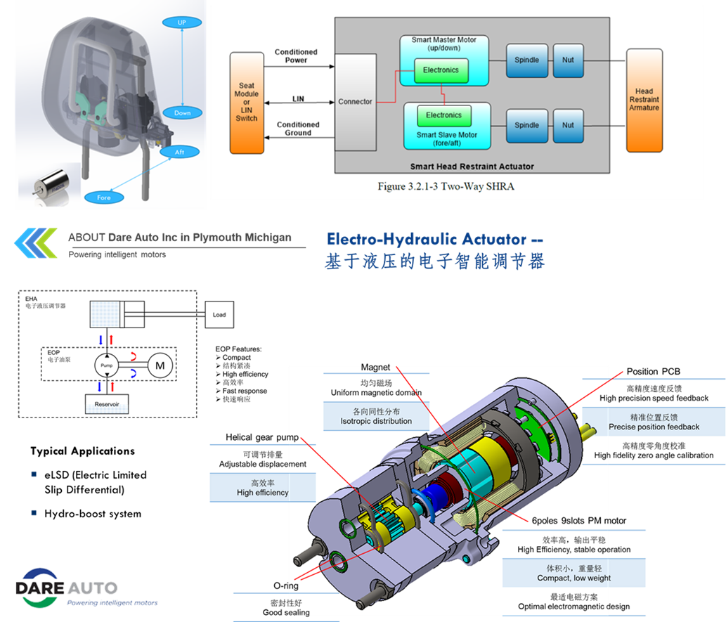
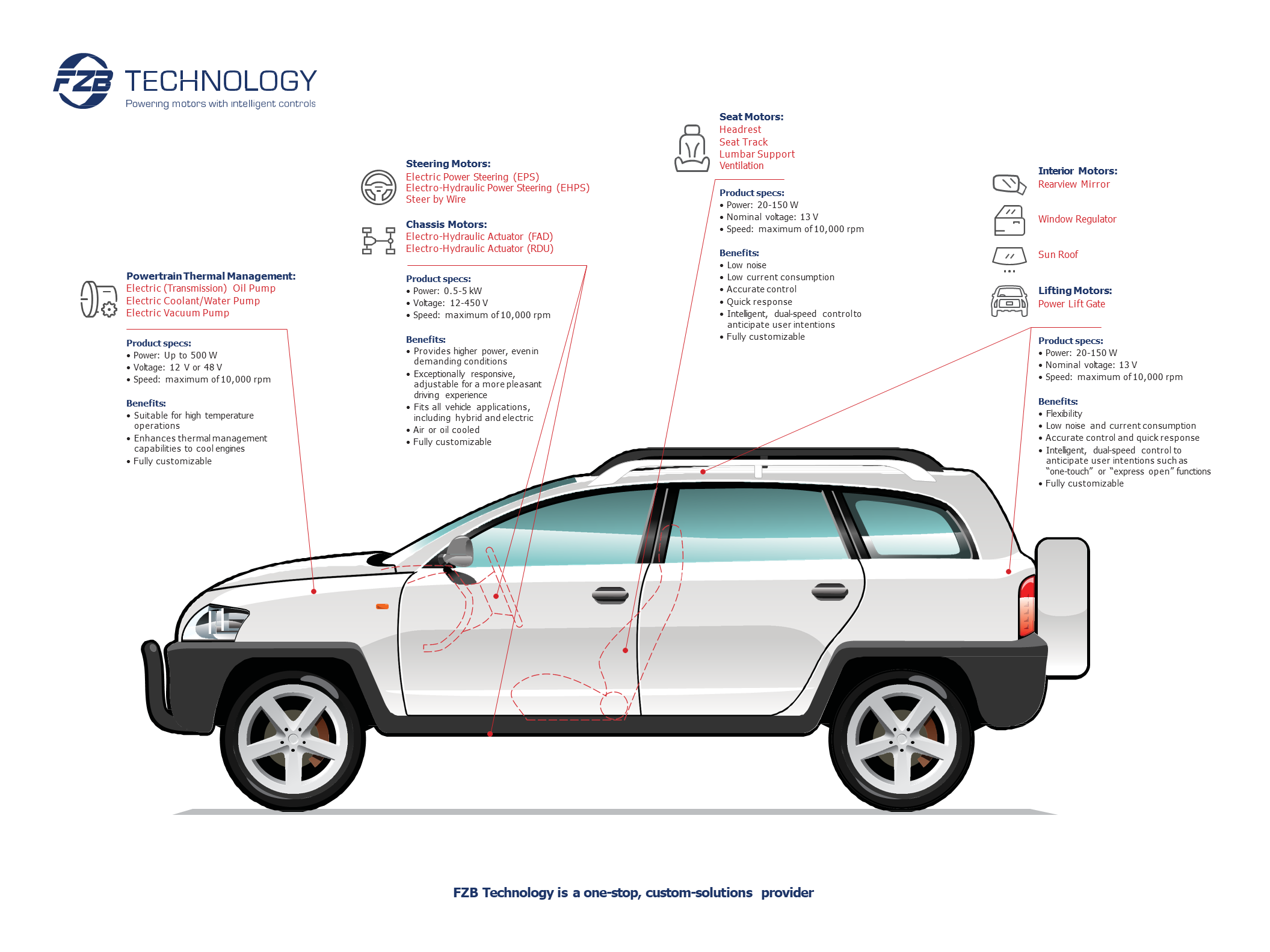
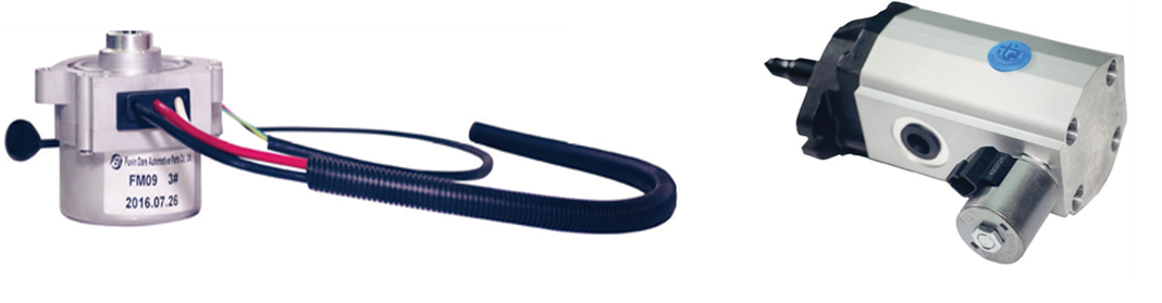
Head Restraints & Window BLDC Motor and Controller
How Headrest BLDC Works:
- Application microcontroller connected to the seat module power output or the vehicle power through the OEM specified connector.
- Interface to LIN as a slave.
- Optional interface to the seat switch
- Master BLDC motor
- Slave BLDC motor for two-way operations
- Motors spin a spindle
- Each spindle connects directly to the nut which moves the head restraint armature
- The motors are bolted to the frame of the head restraint.
Window Regulator Brushless Motor:
- Much better NVH performance – soft start and soft stop, insignificant inrush current, no mechanical stop noise at top or bottom, no relay clicking, and/or mechanical hard start/stop noise.
- Programmable Window Travel Speed – Constant speed, Express-Up & Down via Switch IF or via LIN command with bus voltage ranging from 9V to 16V.
- Meets anti-pinch maximum force requirements for unsupervised window moves – A “real” torque control enables better pinch force control.
- Vehicle Shipment Mode – Prevents the window from moving down due to long-term
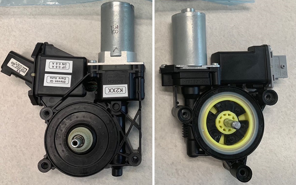 vibrations and meets the current requirement for sleep mode or quiescent current.
 - LIN Diagnostics, Calibration, and Boot Strap Loader.
- FOC Torque control – Shortened time delay for anti-pinch activation and leads to a reduction in torque ripples.
- Speed is higher under the same torque (natural mechanical property).
- Capable of running at overloaded conditions.
- More Reliable – No brush dust or sparking and low EMI, without relay clicking with solid-state power bridge.
- Our data showed our WR brushless motors are quieter and lighter than existing brushed WR motors – 29.8% improvement in NVH and 23% lighter.
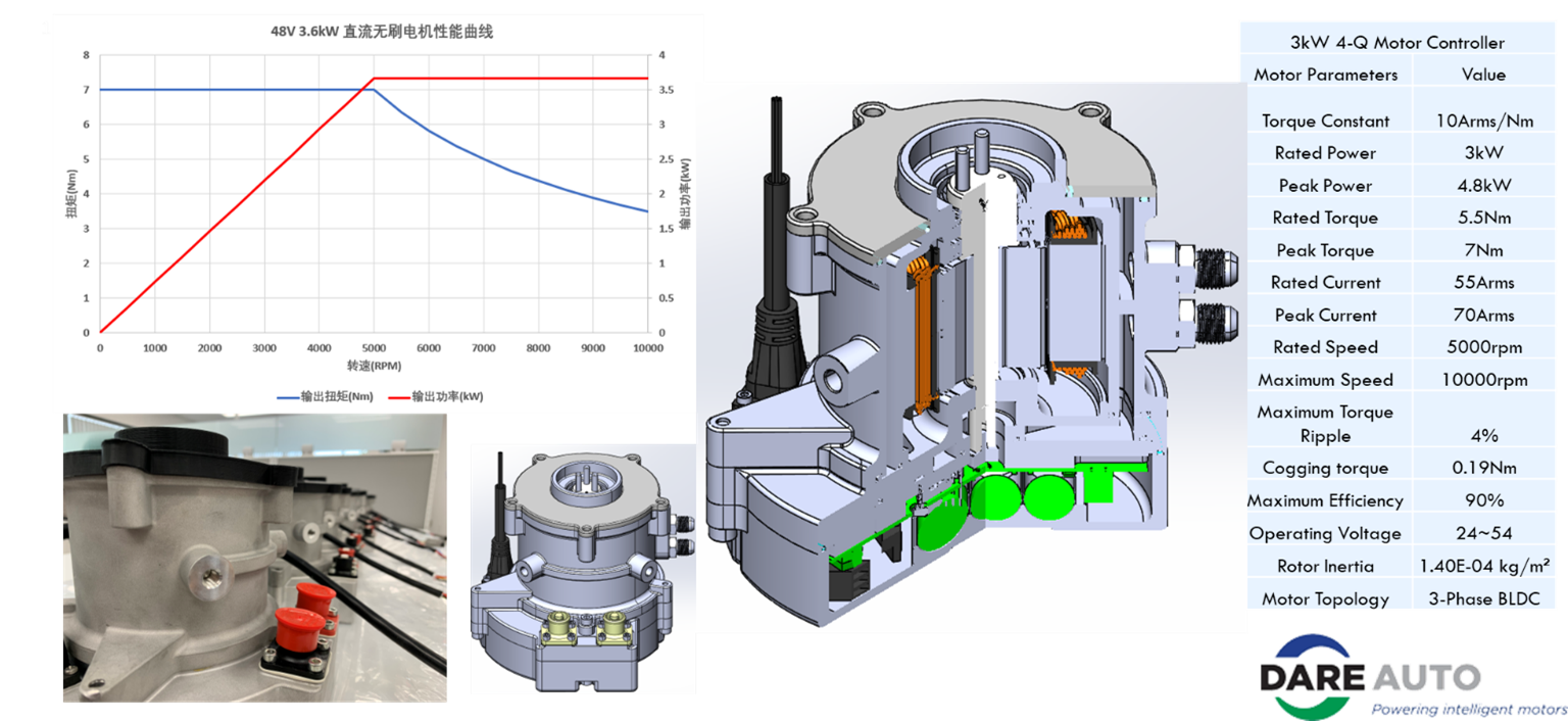
48V 3KW 4-Quadrant Motor Controller – 48V 3KW
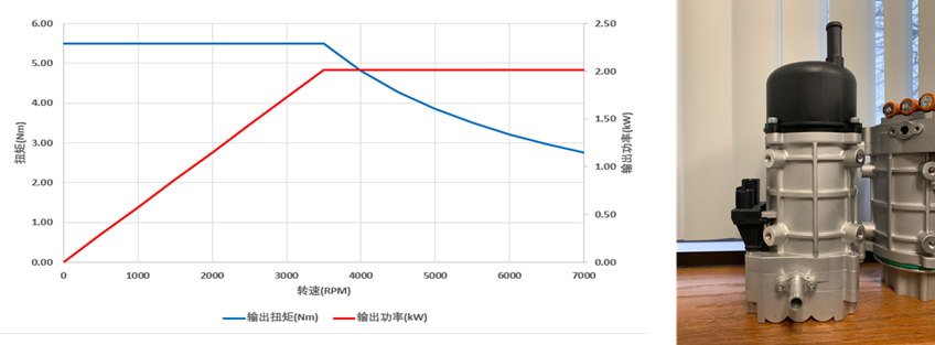
24V EHPS — 24V
A 24V electric system assists the combustion engine while lowering current draw and improving fuel economy by 10% to 15% (3~5% fuel economy for EHPS only). Optimized integration of pump, motor, and controller improves overall efficiency, guarantees mounting compatibility, and implements a flexible control strategy.
 Transmission EOP products
- Integrated/split Module EOP
- Pump Displacement:4ml/r, 2.0ml/r, 4.1 ml/r
- Motor:BLDC(sensored or sensorless control)
- Max Pressure:5 bar, 2.0Mpa
- Max Speed:2200rpm~3000rpm
- Operating Voltage :9~16V(12V)
- Temp:-30-100℃ or -40-105 ℃
- Power:150W~350W
- Data Network: CAN 2.0B
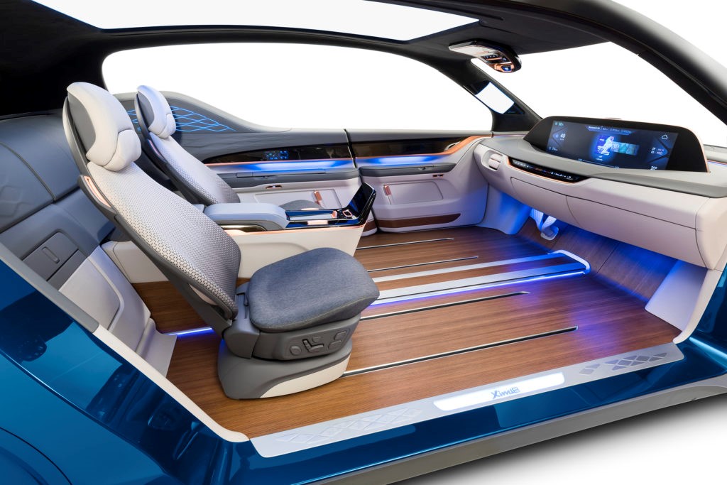
 Advanced People / Goods Mover Powered Seat Rail Concept
This design development is to meet next generation dual speed seat adjustment for Adaptable People Movers and other vehicle applications. Design / Application target is integration of the feature with limited to no change to electrical system architecture or seat module currently standard on all vehicles.
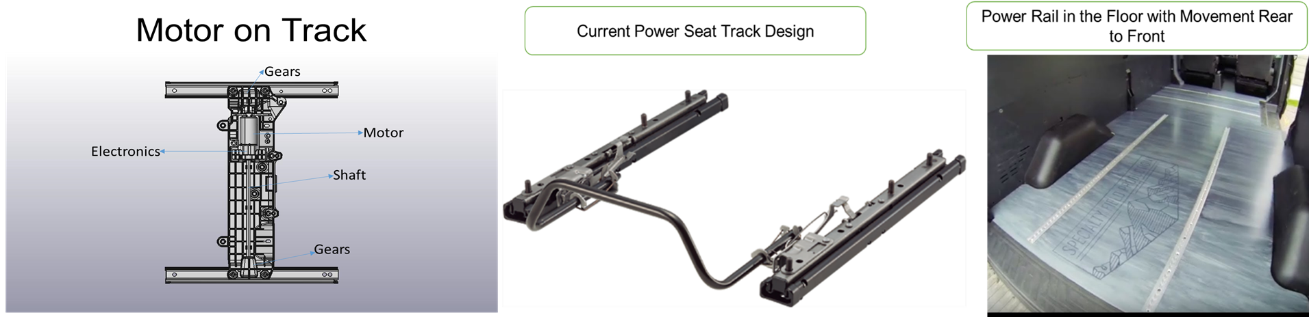
There are multiple Open Issues as of now. Below is initial design information on brushless motor design.
Key Features of Dare-Auto Brushless Seat Motors:
- Dare Auto Motor FM31
- Customizable Motor with integrated electronics.
- Electronics designed to support LIN interface coupled with Blue-Tooth.
- Drop in Replacement
- Gear box for 300mm/sec speed
- 12A to 24A at 12.3v
- Noise < 50dB
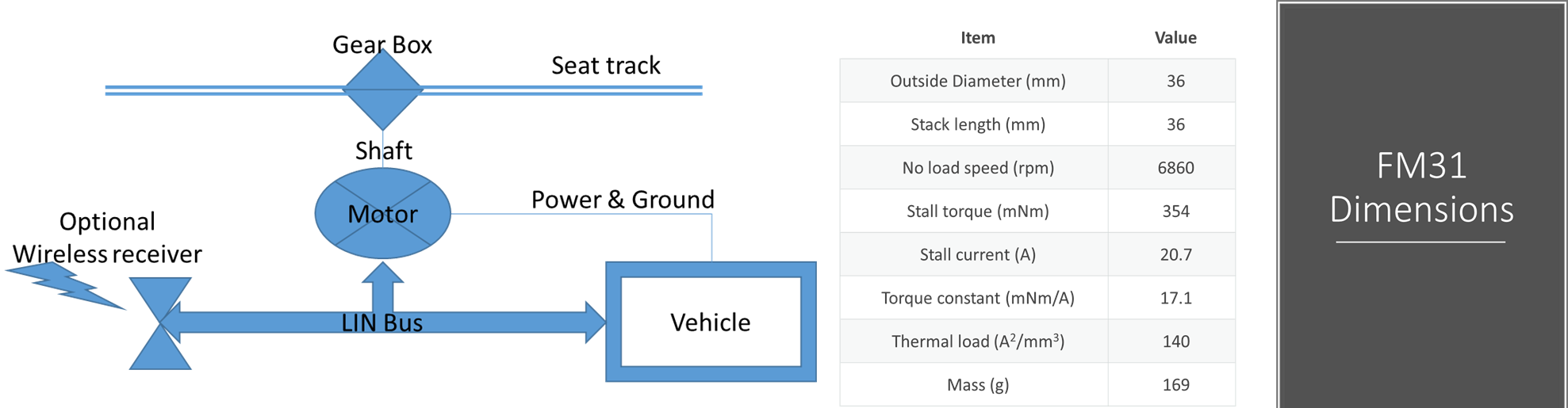
Dura-Auto FM31 Motor Parameters:
- Fast to market and customizable
- BLDC benefits: quiet (~ 3 sones), durable (over 2 million activations), low power consumption, compact and microcontroller to implement features: dual speed, obstacle detection.
- Standard Motor Control Interface through LIN / Bluetooth.
- Speed and Position commands
- Speed and Position Status
- Memory operation
- Optional Wireless Interface
- Power range 10W-60W
- Running change/drop in replacement/self-contained
- The Dare Auto BLDC motor has MOSFET driver to control speed rather than a 1-speed noisy relay in the brush motor.
- Fewer wires reduce vehicle weight: Battery, Ground and LIN only.

For more information on brushless motor integration contact www.dare-auto.com or designhmi@gmail.com.
Dare-Auto Brushless Motors for Seat & Auto Interiors and Exteriors
Brushless DC (BLDC) motors for various seat applications, including headrest, seat track, lumbar support and ventilation. Other interior / exterior applications are lifting motors for window regulators, power lift gates, motors for sun roofs and rearview mirrors.
Dare-Auto BLDC motors are low noise, consume low currents, providing accurate control and quick response. For window regulator application are intelligent – dual-speed controls for “express open” or “one-touch” features. Other applications are for any interior application that needs low noise, higher efficiency & reliability as well as smart electronic controls embedded in the motor.
Dare-Auto BLDC in various Applications Designs have been validated for feature improvement, higher reliability, weight & cost reduction. Despite these advantages application in current Automotive OE’s seems to be a hard sell!
- Fast to market and customizable
- BLDC benefits: quiet (~ 3 sones), durable (over 2 million activations), low power consumption, compact and microcontroller to implement features.
- Standard Motor Control Interface through LIN
- Speed and Position commands
- Speed and Position Status
- Memory operation
- Optional Wireless Interface for exterior application such as running board
- Power range 10W-40W
Dare Auto Liftgate Proposal Summary
- Features: Dare Auto Autonomous Handsfree Liftgate System proposal
- New feature – Normal and express dual speed
- New feature – Obstacle detection
- New feature – Gesture recognition
- Running change – Self-Contained
- Network LIN compatible (Fob in range to activate gesture, command to open/close, status) +battery & ground.
- 2x longer life
- 40% lower power consumption suitable for electric vehicles
- 8dB Quieter (~ 3 sones)
- Retrofits in the existing space with fewer wires.
Competitive Analysis Over Incumbent Liftgate Designs
- The Dare Auto BLDC motor has MOSFET driver to control speed rather than a 1-speed noisy relay in the brush motor.
- 25% assembly cost save.
- The Dare Auto proposal has the BLDC motor benefits advantage over the brush motor.
- The Dare Auto BLDC motor is sealed for longer life.
- The Dare Auto proposal has a wiring harness advantage as the power PWM wire lengths are eliminated and it uses 1 wire LIN instead. This reduces the vehicle weight.
Dare Auto Running Board Proposal Summary
- Features: Dare Auto Autonomous Wireless Running Board System proposal
- New feature – Wireless interface only needs battery & ground wires.
- New feature – Normal and express dual speed
- New feature – Obstacle detection
- Running change – Self-Contained
- 2x longer life
- 40% lower power consumption suitable for electric vehicles
- 8dB Quieter (~ 3 sones)
- Retrofits in the existing space with fewer wires.
Competitive Analysis Over Incumbent Running Board
- The Dare Auto proposal has a wireless interface eliminating all wiring other than power+ground. This reduces the vehicle weight and increases reliability.
- The Dare Auto BLDC motor has MOSFET driver to control speed rather than a 1-speed noisy relay in the brush motor.
- Comparable Cost
- The Dare Auto proposal has the BLDC motor benefits advantage over the brush motor.
- The Dare Auto BLDC motor is sealed for longer life.
For more Application information CLICK:
- Automated Power Lift Gate – http://www.designhmi.com/2018/06/20/automatic-powered-rear-lift-gate/
- Powered Retractable Running Board – http://www.designhmi.com/2018/06/19/powered-retractable-running-board/
For more information write to designhmi@gmail.com.
Advantages over brushed motors:
- Quieter: spins at higher speed inaudible to humans.
- Reliability: no brushes that can break.
- Higher efficiency: no added resistance to current flow from brushes and lower electromagnetic emissions.
- Built-in electronics: smooth control over operating range, diagnostics and configuration
- No Hall Sensor.
- Only 3 wires (PWM).
- Memory Position from number of rotor spins
Sensor-Less Motor Alternative: Seats, Haptics & Climate Control
Automotive interiors still use brushed motors despite the obvious advantages of brushless, primarily because in current market there is a price premium for brushless motors.
The other option is Piezo motors but these are primarily designed for micro motion and not torque and thus in most cases not ideal for most automotive applications.
There are substantial advantages to brushless and when evaluated over an entire system the cost penalty could be a save.
Advantages of Brushless over brushed motors:
- Noise reduction.
- Very low vibration
- Reduced EMC concerns.
- Size & weight reduction.
- Feature add through speed control.
- Reliability and quality.
- Integration of gear mechanism.
- Higher efficiency.
Basuic design requirements are capabity to operate through enviromental extremes of -40C to 85C with operating voltage from 8v to 16v – nominal voltage 13.2v.
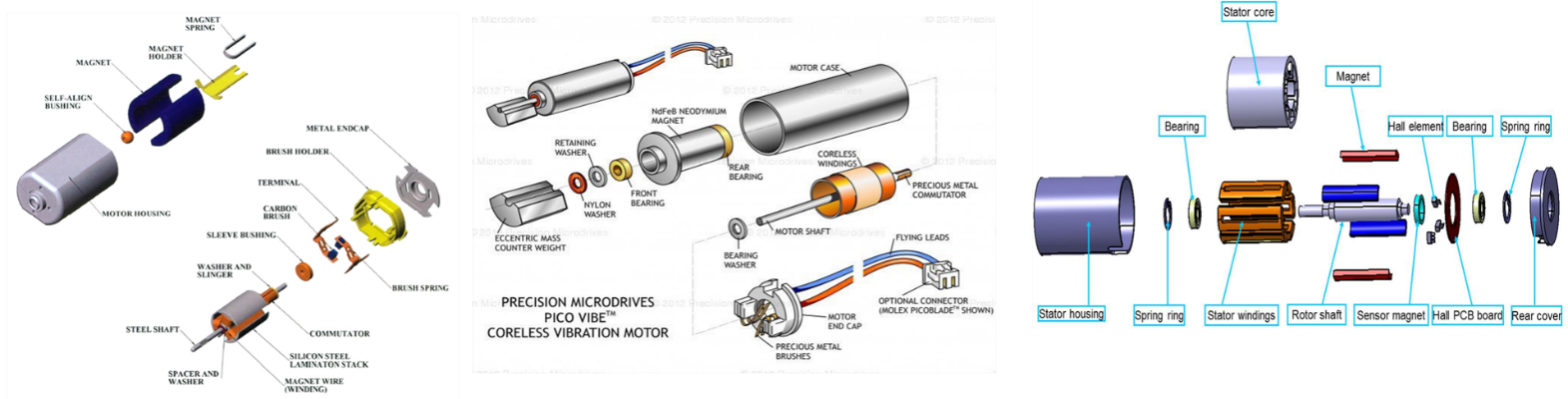
Below is basic Bill of Material comparison between brushed and brushless:
| # | Description | Brushed | Brushless |
| 1 | End Cap / Rear Cover | X | X |
| 2 | PCBA | – | X |
| 3 | Hall Sensor | – | X |
| 4 | Brush Cover | X | – |
| 5 | Brushes | X | – |
| 6 | Shaft | X | X |
| 7 | Housing / Stator | X | X |
| 8 | Coreless Rotor / Coil | X | X |
| 9 | Washer / Ball bearing w/support | X | X |
| 10 | Magnet | X | X |
| 11 | Retaining Ring / Spacer | ||
| 12 | Terminals / Pigtail | X | X |
| 13 | Minor Misc. Parts | X | X |
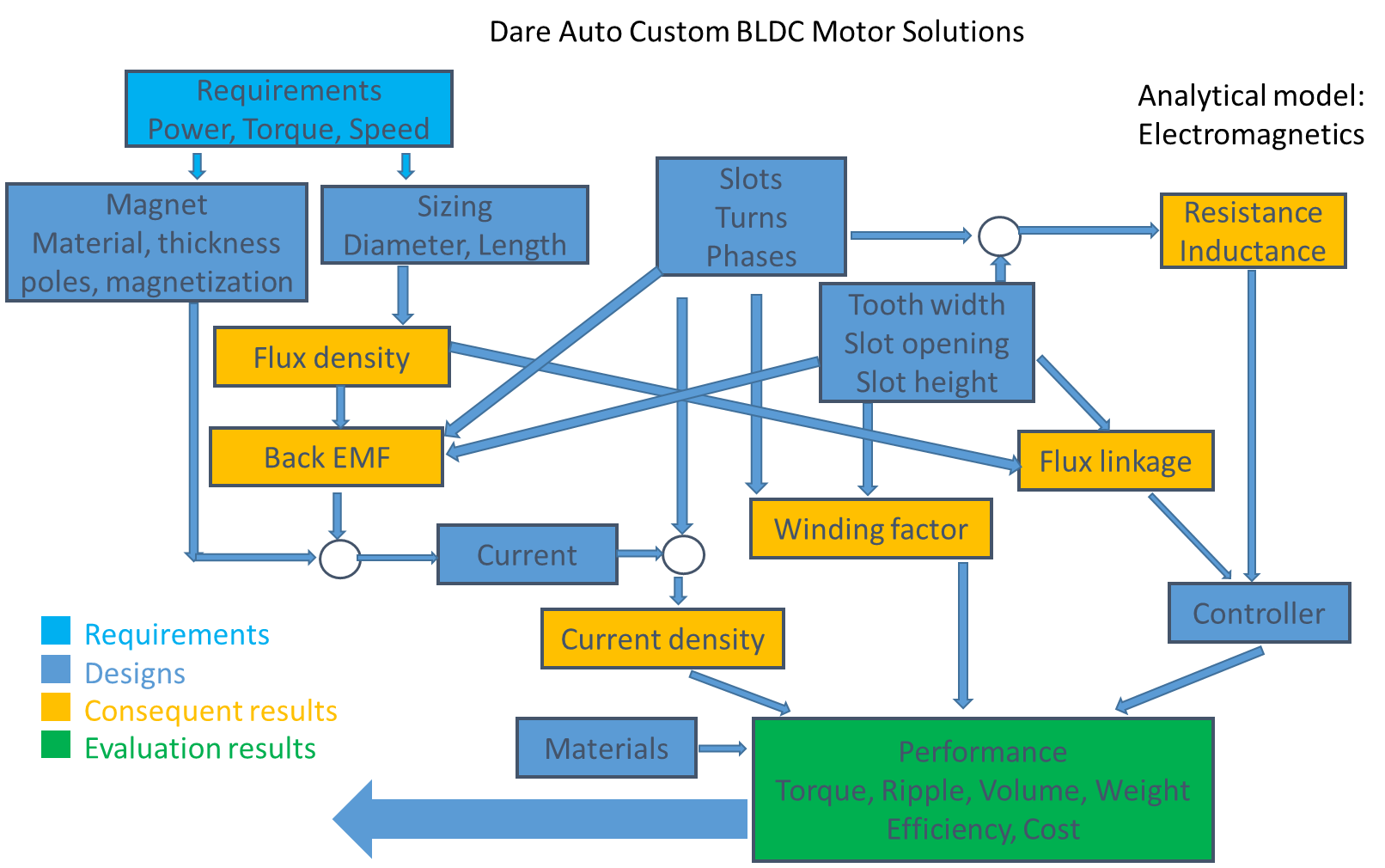
Overview:
From an economic point of view, a brushless DC motor should always be cheaper than a DC motor if designed for the same specification, since it basically is a brushed DC motor without the brushes.
What make it more expensive are two facts.
- A brushless DC motor needs a controller
- A controller needs some kind of feedback from a sensor (usually hall or MR sensors)
To make brushless DC motors more economically viable, there are few solutions:
Centralize control and use a bus system: Cars have lots of electronics anyway and to add elements that allow the control of multiple motors throughout the car would not add a lot to the manufacturing cost of the electronics for the car. It would be almost unrecognizable. This can only be done by the system integrator who assures that the motors are compliant with his control scheme.
Use self-sensing coil technology instead of additional sensors:
- Depending on the motor manufacturing technology, sometimes it may just be easier and cheaper to use hall sensors, but today you can actually use the motor coils themselves to detect rotor position by back-EMF detection and therefore get rid of the sensors.
http://www.atmel.com/images/doc8012.pdf.
http://cache.freescale.com/files/product/doc/AN1914.pdf
- The sensor less control has the additional advantage of needing fewer connections. Additionally you can use every BLDC motor also as a sensor. When there is more resistance to the movement you are trying to perform, the controller has to increase the current to get the job done. This current increase is equivalent to the resistance the motor encounters. This way you can get force feedback by a simple current measurement. This could serve to replace pressure and other sensors that would otherwise be used in such cases.
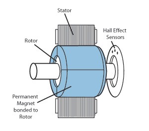
The basic explanation of a brushless motor’s construction is that it is like a brushed motor, except 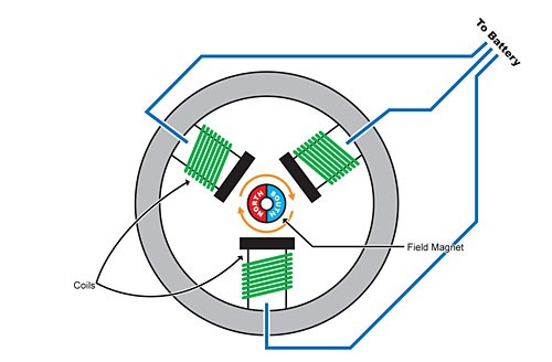 everything is ‘inside out’ and there are no brushes at all. The permanent magnets that would wrap around the armature in a normal motor are instead placed around the motor shaft, and this assembly is called the rotor. The wire coils are around the inside of the motor can, making several different magnetic poles. Most are designed with sensors on the rotor that send signals back to the electronic speed control.
Refer http://www.hpiracing.com/en/brushless
 If you do not need speed control but only need to know position just add a very small sensor on the rotor, plus an extra set of thin wires that connect the motor to the speedo. That will tell the speedo the position of the motor’s armature as it spins, hundreds of times per second.
As no speed control is needed and position is controlled by external module and the motor armature spins when power is applied.
In this design coils are moved to the stator, where they are connected to the controlling IC.
Digital commutation and linear soft-switching eliminates the sparks and therefore RFI interference. The fully integrated A1442 Hall-effect device and precision amplifier are coupled to an internal full 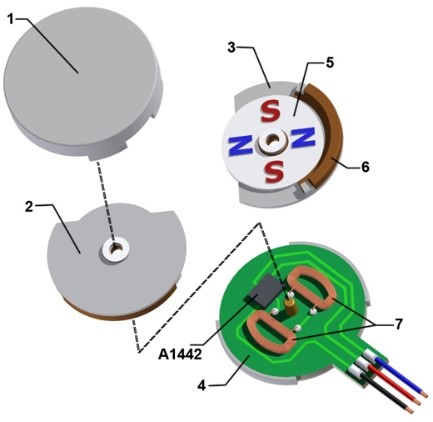 bridge output through comparator circuitry that determine the proper commutation points. The third wire shown in the motor of figure 4 is optional, connecting to an enable pin on the A1442 that can be used to control the active braking and sleep functions. This third wire can be eliminated by tying the IC pin to VCC on the PCB.
The A1442 is the only IC necessary to drive the motor.
Stepper motors advance the rotor in finite increments; the shaft stays fixed until moved again. They are synchronous DC motors without brushes or contacts; but with magnetic fields electronically switched to rotate the armature magnet around, converting digital pulses into shaft rotation.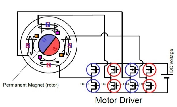
A stepper is a synchronous DC motor that divides a full rotation into a discrete number of steps; the number of steps is equal to the number of electromagnets arranged around a central core. By controlling the current to these magnets, the motor can be turned by a precise angle. Steppers are typically driven by H-bridges under PWM control. H-bridge rotation angle is proportional to the number of pulses, and rotational speed is proportional to the frequency of the pulses. One example of a good H-bridge driver for robotics is the Texas Instruments DRV8313, with three individually controllable drivers
For a 3-phase brushless DC motor – you’d need to change commutation order, this is slightly more complex because how to do that depends on what kind of position sensor is being used. For simple applications like headrest you can simply swap any two of the phase connections. 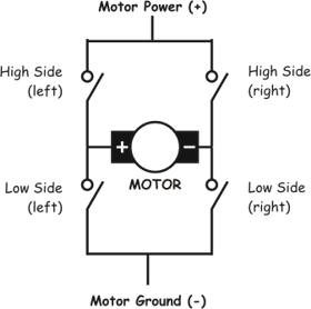
Usually H-bridge is one way of interfacing a DC motor. These days many IC manufacturers have H-bridge motor drivers available in the market like L293D is most used H-Bridge driver IC.
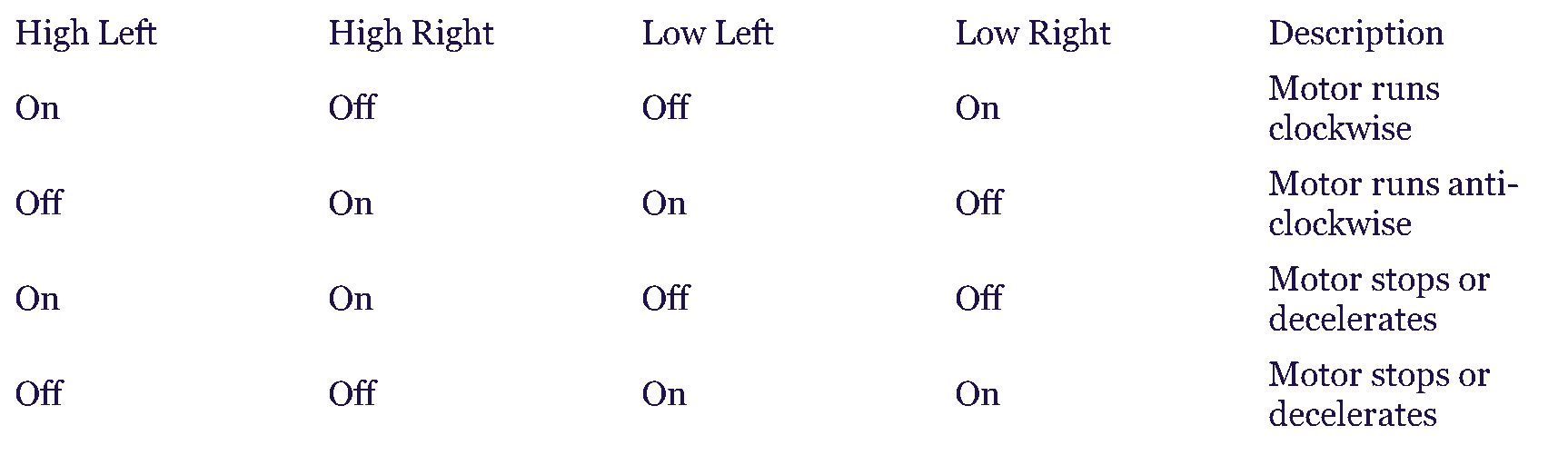
As you can see in the figure above there are four switching elements named as “High side left”, “High side right”, “Low side right”, “Low side left”. When these switches are turned on in pairs motor changes its direction accordingly. Like, if we switch on High side left and Low side right then motor rotate in forward direction, as current flows from Power supply through the motor coil goes to ground via switch low side right.
H-bridge can be made with the help of transistors as well as MOSFETs, the only thing is the power handling capacity of the circuit.
Refer http://www.studyelectrical.com/2015/07/how-to-change-direction-of-dc-motor.html
Infineon’s motor control solutions achieve more using less. The NovalithIC™ family lets engineers  create extremely compact solutions in motor control with high power capabilities. With integrated over-/under-voltage, over temperature, and overcurrent protection, as well as embedded analog current sense and status flag diagnosis, NovalithIC™ brings high-current motor drive capabilities in a small package—with low path resistance down to 6mOhm and high-current capability up to 68 Amps.
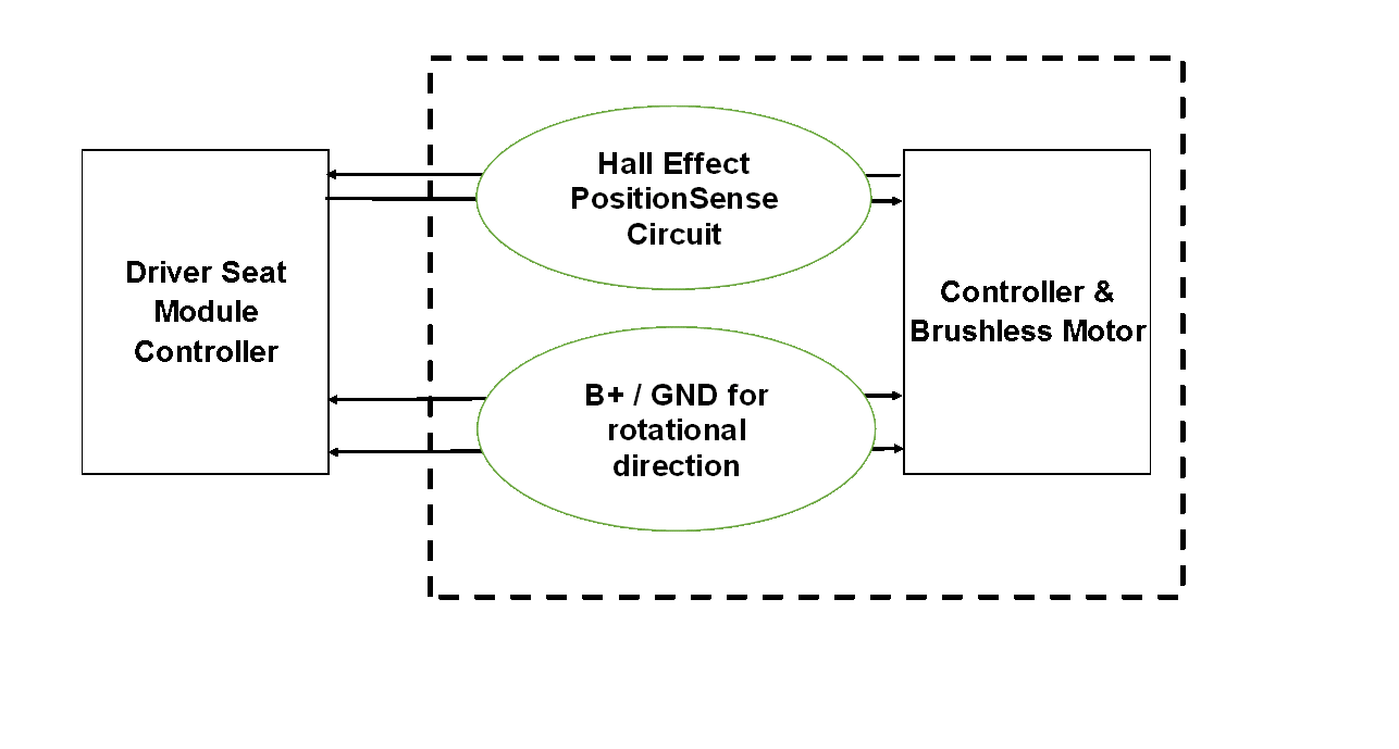
Concept block diagram of brushless motor controller for direct replacement of brushed motor in automotive seats and other applications – no speed control.
For more information contact FZB Technologies or write to designhmi@gmail.com

Hello! I just would like to give you a huge thumbs up
for your great info you have here on this post.
I’ll be returning to your web site for more soon.