
Flexpoint Impact Detection Sensor
The impact detection system is covered by U.S. patent 6,392,527
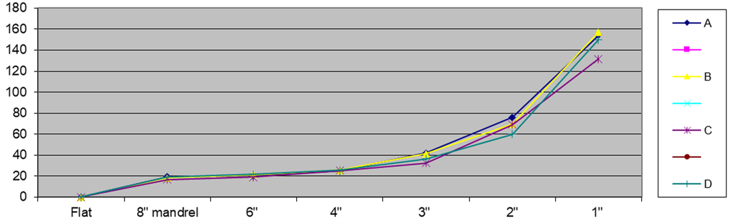
The Bend Sensor® works by stressing the resistive ink. The bending or stretching that causes tensile stresses to increase the resistance. Compressive stresses do not respond the same. The resistance change is based on the bend radius as well as the angular deflection. The smaller the radius or the greater the angular deflection, the greater the change. The change can increase by orders of magnitude. As long as the yield point of the material is not exceeded the sensor will return to its original value.
The table shows the actual resistance changes as bent around the various radii. The sensor is a standard Flexpoint 3” long base sensor.
In the case of an impact, the sensor is mounted, usually using pressure-sensitive adhesive to the backside of the fascia of the vehicle. Based on the object creating the impact, the energy is transferred into the system at different rates. The following graph shows two examples of impacts. The same sensor was used in each of the 6 impacts tested.
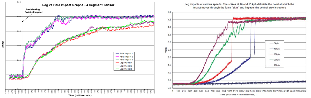
The data was acquired using a 5VDC supply, 33K ohm reference resistor, and an oscilloscope. Data was taken at 100K Hz. Subsequent data have been collected at 1K Hz. A membrane switch was attached to the front of the fascia to detect the impact. The data was clipped at 10 milliseconds.
The Bend Sensor® electrical integration:
- The sensor can be configured to have the electronics mounted to the sensor and process the events and send decisions to the vehicle’s body controller or be connected directly to the vehicle to process the events.
- Environmental considerations are filtered out because of the speed, and magnitude of the sensor’s output during the impact event.
- Small, low speed i.e., low energy impacts can be detected as well as those noted above.
- Bumper/fascia damage can be compensated for by allowing the electronics to adjust to a new baseline, thus eliminating the need to replace the sensor.
- The typical failure mode for the sensor is an open circuit.
- More information is available upon request including 3rd party tests.
Front & Rear Fender Impact Detection:
Designed for low-speed impacts. Impacts that have energies less than 7 joules, which amounts to dropping a bowling ball from 4 inches. This we can read as well as the 25 KPH impacts shown in the presentation.
Basic Construction of Flexpoint Sensor:
- The sensor can be configured to have multiple individually read zones for positional data.
- The sensor can also be a single element that just registers an impact on the fascia.
- The sensor is attached typically using a pressure-sensitive adhesive to the reverse side of the fascia.
- Electronics modules can be mounted and potted to the end of the sensor or remotely.
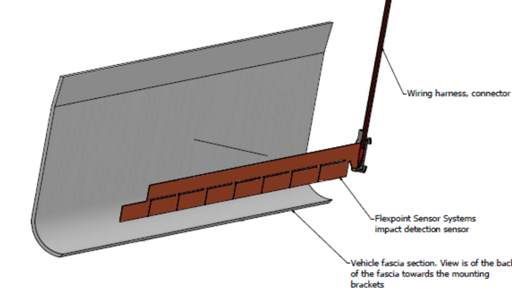
- Another option would be to have the vehicle’s control module programmed to monitor the sensor.
For more information email Clark Mower, President CEO clark@flexpoint.com or Dave Beck at dave@flexpoint.com or bbedi@designhmi.com
