One of the challenges going from Brushed Motor to Brushless is the system change for simple functionality. A brush motor needs only B+ and GND for two wire input to function. A brushless normally needs minimum three wire input – B+, GND and Signal Line as more control electronics are integrated into brushless motor core design.
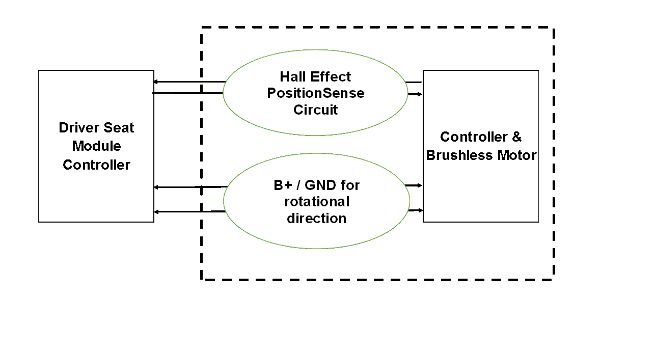
Below is concept interface design using Microchip IC which can allow Vehicle System Designers replace high noise / high power brush motors with low noise / lower power / higher reliability brushless motors.
Applications are automotive comfort / convenience applications.
 Automotive interiors still use brushed motors despite the obvious advantages of brushless, primarily because in current market there is a price premium for brushless motors.
The other option is Piezo motors but these are primarily designed for micro motion and not torque and thus in most cases not ideal for most automotive applications.
There are substantial advantages to brushless and when evaluated over an entire system the cost penalty could be a save.
Advantages of Brushless over brushed motors:
- Noise reduction.
- Very low vibration
- Reduced EMC concerns.
- Size & weight reduction.
- Feature add through speed control.
- Reliability and quality.
- Integration of gear mechanism.
- Higher efficiency.
Basuic design requirements are capabity to operate through enviromental extremes of -40C to 85C with operating voltage from 8v to 16v – nominal voltage 13.2v.
Below is basic Bill of Material comparison between brushed and brushless:

Overview:
From an economic point of view, a brushless DC motor should always be cheaper than a DC motor if designed for the same specification, since it basically is a brushed DC motor without the brushes.
What make it more expensive are two facts.
- A brushless DC motor needs a controller
- A controller needs feedback from a sensor (usually hall or MR sensors)
To make brushless DC motors more economically viable, there are few solutions:
Centralize control and use a bus system: Cars have lots of electronics anyway and to add elements that allow the control of multiple motors throughout the car would not add a lot to the manufacturing cost of the electronics for the car. It would be almost unrecognizable. This can only be done by the system integrator who assures that the motors are compliant with his control scheme.
Use self-sensing coil technology instead of additional sensors:
- Depending on the motor manufacturing technology, sometimes it may just be easier and cheaper to use hall sensors, but today you can use the motor coils themselves to detect rotor position by back-EMF detection and therefore get rid of the sensors.
http://www.atmel.com/images/doc8012.pdf.
http://cache.freescale.com/files/product/doc/AN1914.pdf
- The sensor less control has the additional advantage of needing fewer connections. Additionally, you can use every BLDC motor also as a sensor. When there is more resistance to the movement you are trying to perform, the controller must increase the current to get the job done. This current increase is equivalent to the resistance the motor encounters. This way you can get force feedback by a simple current measurement. This could serve to replace pressure and other sensors that would otherwise be used in such cases.
In normal design comparison between brushed and brushless motors for similar application the following quality improvement was clearly established:
- Brushless motor 30% quieter than current brushed motor solution.
- Brushless motor was 23% lighter than comparable current brushed motor solution
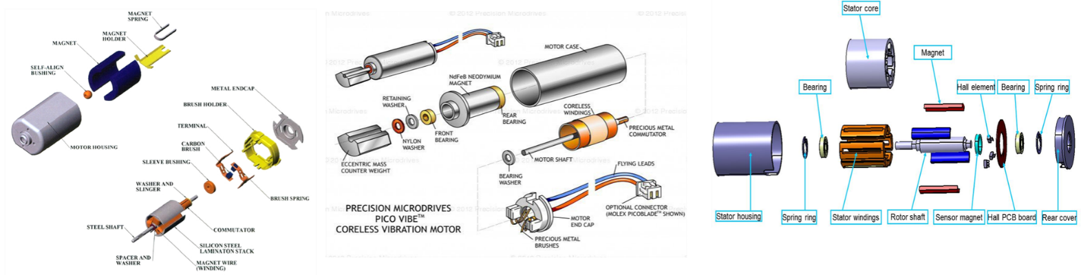
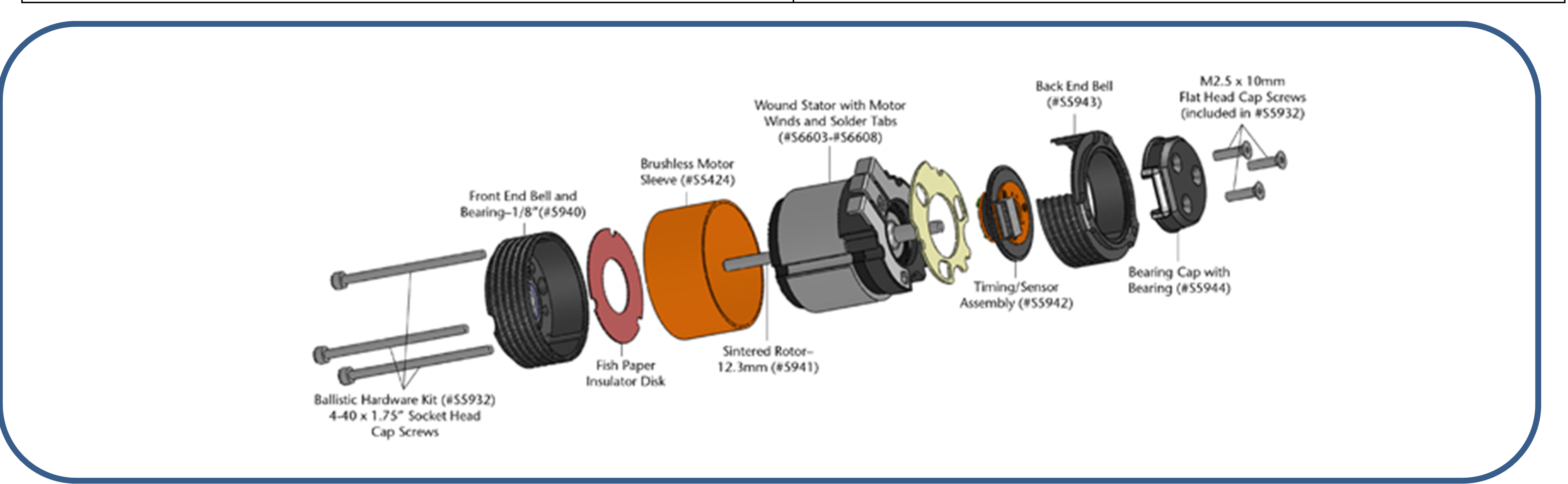
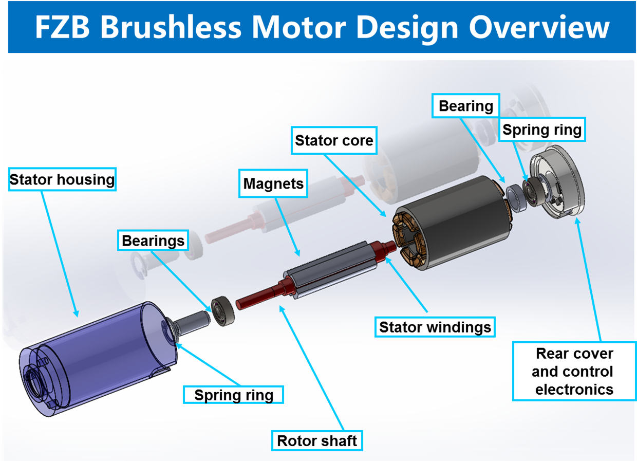
The basic explanation of a brushless motor’s construction is that it is like a brushed motor, except everything is 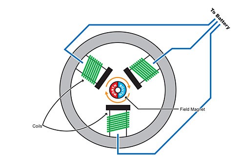 ‘inside out’ and there are no brushes at all. The permanent magnets that would wrap around the armature in a normal motor are instead placed around the motor shaft, and this assembly is called the rotor. The wire coils are around the inside of the motor can, making several different magnetic poles. Most are designed with sensors on the rotor that send signals back to the electronic speed control.
Refer http://www.hpiracing.com/en/brushless
If you do not need speed control but only need to know position just add a very small sensor on the 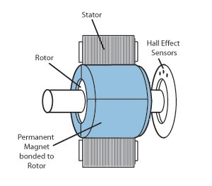 rotor, plus an extra set of thin wires that connect the motor to the speedo. That will tell the speedo the position of the motor’s armature as it spins, hundreds of times per second.
As no speed control is needed and position is controlled by external module and the motor armature spins when power is applied.
In this design coils are moved to the stator, where they are connected to the controlling IC.
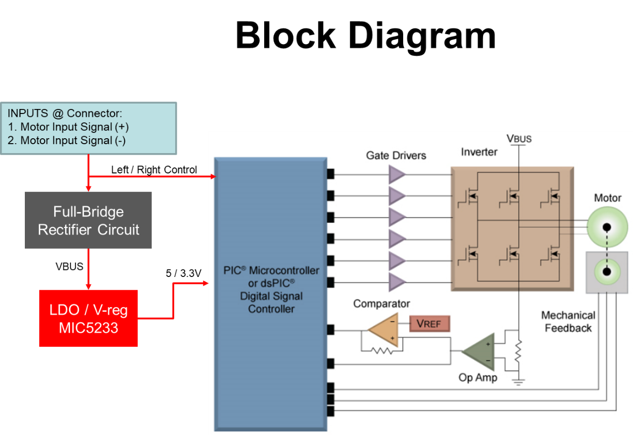
Digital commutation and linear soft-switching eliminates the sparks and therefore RFI interference. The fully integrated A1442 Hall-effect device and precision amplifier are coupled to an internal full 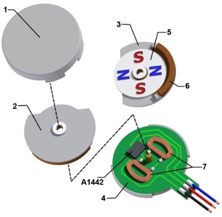 bridge output through comparator circuitry that determine the proper commutation points. The third wire shown in the motor of figure 4 is optional, connecting to an enable pin on the A1442 that can be used to control the active braking and sleep functions. This third wire can be eliminated by tying the IC pin to VCC on the PCB.
The A1442 is the only IC necessary to drive the motor.
Stepper motors advance the rotor in finite increments; the shaft stays fixed until moved again. They are synchronous DC motors without brushes or contacts; but with magnetic fields electronically 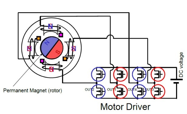 switched to rotate the armature magnet around, converting digital pulses into shaft rotation.
A stepper is a synchronous DC motor that divides a full rotation into a discrete number of steps; the number of steps is equal to the number of electromagnets arranged around a central core. By controlling the current to these magnets, the motor can be turned by a precise angle. Steppers are typically driven by H-bridges under PWM control. H-bridge rotation angle is proportional to the number of pulses, and rotational speed is proportional to the frequency of the pulses. One example of a good H-bridge driver for robotics is the Texas Instruments DRV8313, with three individually controllable drivers
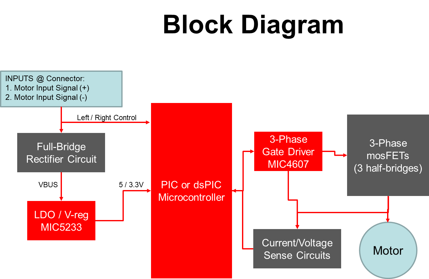
For a 3-phase brushless DC motor – you’d need to change commutation order, this is slightly more complex because how to do that depends on what kind of position sensor is being used. For simple  applications like headrest you can simply swap any two of the phase connections.
Usually H-bridge is one way of interfacing a DC motor. These days many IC manufacturers have H-bridge motor drivers available in the market like L293D is most used H-Bridge driver IC.
As you can see in the figure above there are four switching elements named as “High side left”, “High side right”, “Low side right”, “Low side left”. When these switches are turned on in pairs motor changes its direction accordingly. Like, if we switch on High side left and Low side right then motor rotate in forward direction, as current flows from Power supply through the motor coil goes to ground via switch low side right.
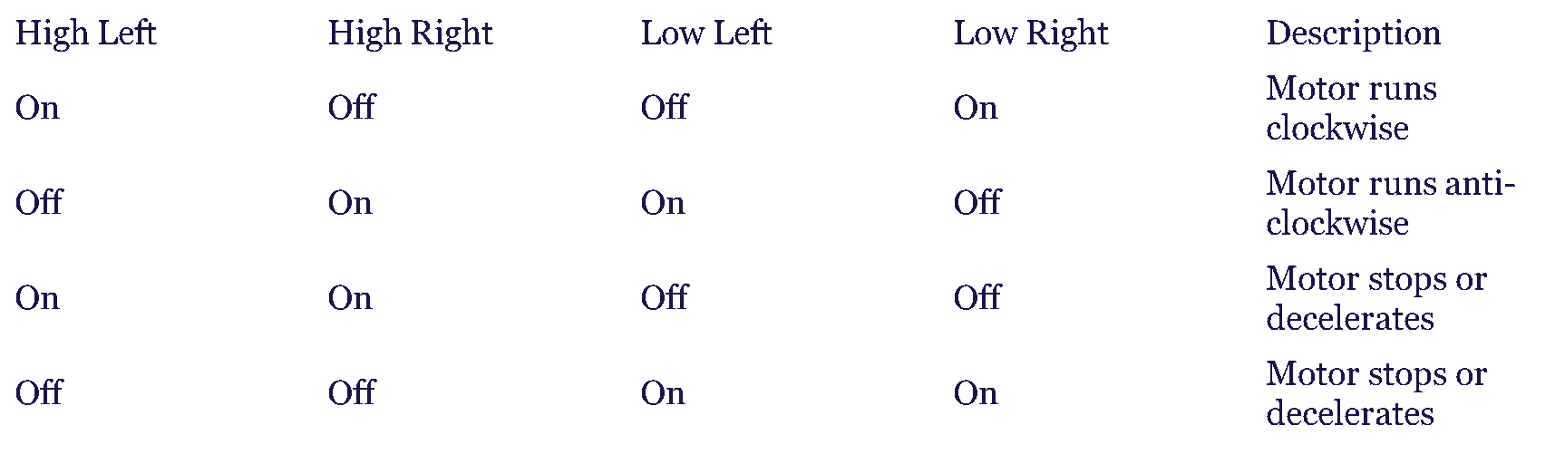
H-bridge can be made with the help of transistors as well as MOSFETs, the only thing is the power handling capacity of the circuit.
Refer http://www.studyelectrical.com/2015/07/how-to-change-direction-of-dc-motor.html
Infineon’s motor control solutions achieve more using less. The NovalithIC™ family lets engineers create extremely compact solutions in motor control with high power capabilities. With integrated  over-/under-voltage, over temperature, and overcurrent protection, as well as embedded analog current sense and status flag diagnosis, NovalithIC™ brings high-current motor drive capabilities in a small package—with low path resistance down to 6mOhm and high-current capability up to 68 Amps.
Concept block diagram of brushless motor controller for direct replacement of brushed motor in automotive seats and other applications – no speed control.