
Heavy Truck Multiplexed Integrated Switch Pack Application Ready Design
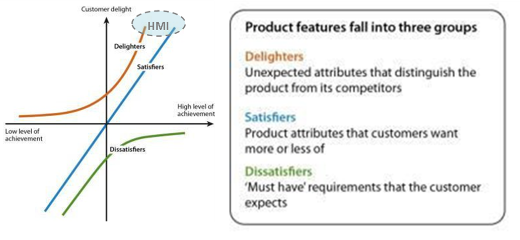
Human Machine Interface products must not only meet the basic functional need but also add to driver comfort convenience, allow for styling options and be ergonomically friendly.
Reliability & Quality is a given so product must meet cost targets to add value. It is for that reason that investigating Implementation Ready (IR) Technologies is very important.
To do that we already know what the current market designs are. In addition, we need to set a direct cost target based on current products. Improving features should not be used as license to increase cost. One easy way to set target is working back on current prices and setting cost target based on 65% direct cost ration to selling price.
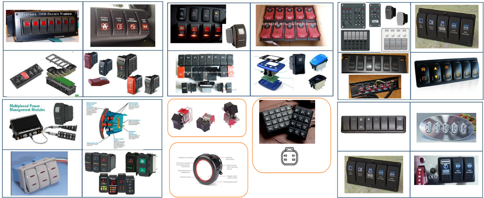
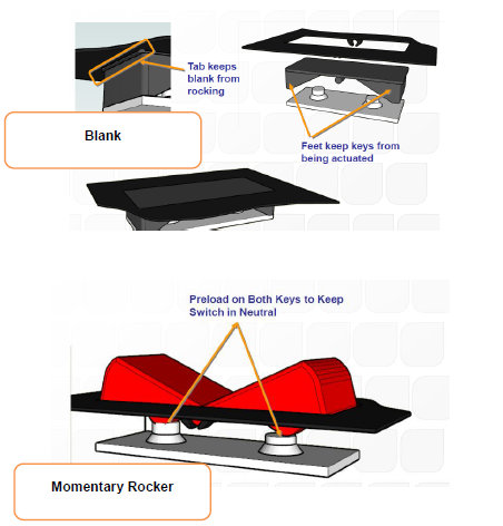
Below are pictures of some current heavy truck switch assemblies.
Target market want would be multiplexed systems. If we design for these same switches could be used for high current applications with an interface relay module with high current terminals.
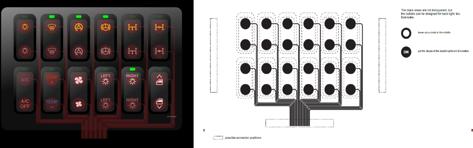
Ideal configuration would be 3×1 modules though the industry uses 2×1, 6×1 and larger switch assembly configurations. However, the larger switch pack requires giving away too many circuits when fewer switches are needed.
A typical system design as below:
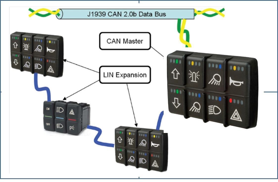
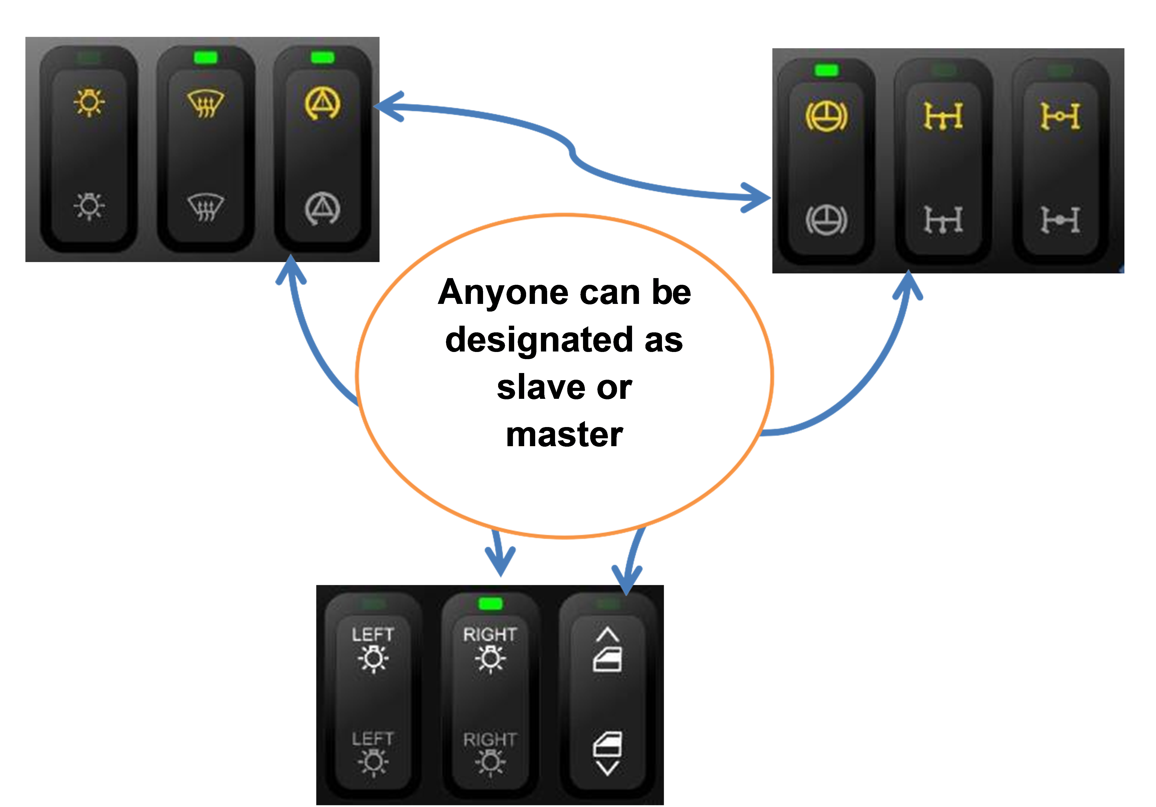
3×1 switch interface bezel will have the functional indicators controlled by PCBA to reduce knob complexity. Based on this system one 3×1 switch module will be the master and other slaves.
Slave switches will communicate to the master through LIN while the master will communicate to the system through J 1939 CAN.
- Al 3×1 switch control boards will have LIN and CAN interface to reduce complexity. Choice of which is Slave module and which Master will be up to the OE.
- There is opportunity here in deleting LIN interface totally and all communication can be CAN though that may add another cut lead in the system. Would need to evaluate impact of same during design reviews.
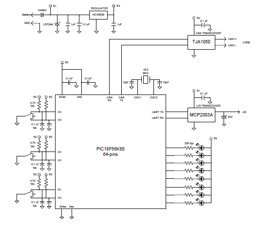
A few basic design parameters for the assembly design providing input on CAN to BCM:
- Common design rocker knobs or minor assembly changes with tool inserts.
- Graphics to be paint & laser etch as required.
- Switch bezel with functional indicators which eliminates knob complexity.
- Common 3×1 assembly body to hold switch & PCBA.
- PCBA with CAN / LIN, control IC, lighting, functions indicator lighting and either gold plated low current contact or silver-plated dome contacts.
- Elastomer keypad with low resistance SC pills to seal electrical components – make switch water resistant.
- Press fit terminals – eliminates separate soldering operation.
- Rear body with connector.
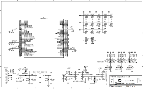
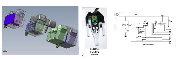
Below is circuit using Microchip IC.
Below is the BOM.
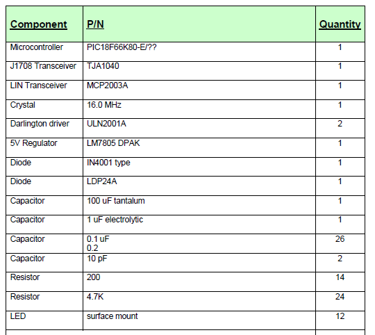
Other Assembly parts as below:
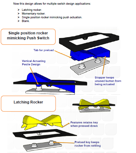
- Keypad designed for push, rocker and latching rocker
- 3 Plastic Caps – push, rocket, latching, indicator or blank
- Switch Bezel & Cover
- Rear Cover with connector shell
- PCBA with LED’s & Connector – CAN & LIN Bus Interface
Note:
- Keypad design with low resistant carbon-nickel alloy pills.
- Plastic caps molding cost based on 8 cavity mold, paint & laser etch.
- Switch bezel includes three mini bezels and master switch cover. Mini bezel has dead font functional graphics that are paint & laser etched.
- Rear cover has connector shell for compliance pin terminals.
- PCBA cost includes BOM of electronic components, 2 sided PCBA, press fit terminals and cost to pick & place SMD’s with reflow solder.
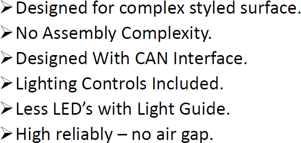
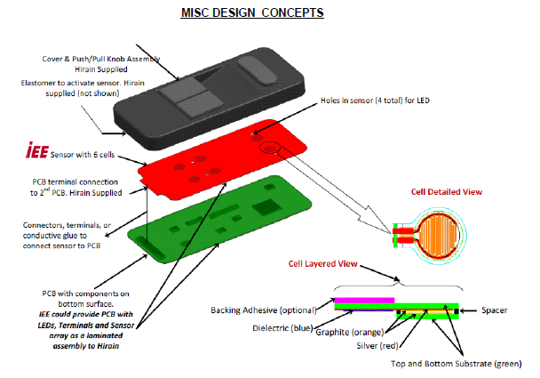
6×2 SWITCH TOUCH PADS
Below is design example of 6×2 capacitive touch pad. It would include CAN / LIN interface with a fully styled 3D surface, sealed and designed for 1 million life cycle actuations.
For more information write to designhmi@gmail.com
