
HTK Engineering – Anti-Rollaway Installation
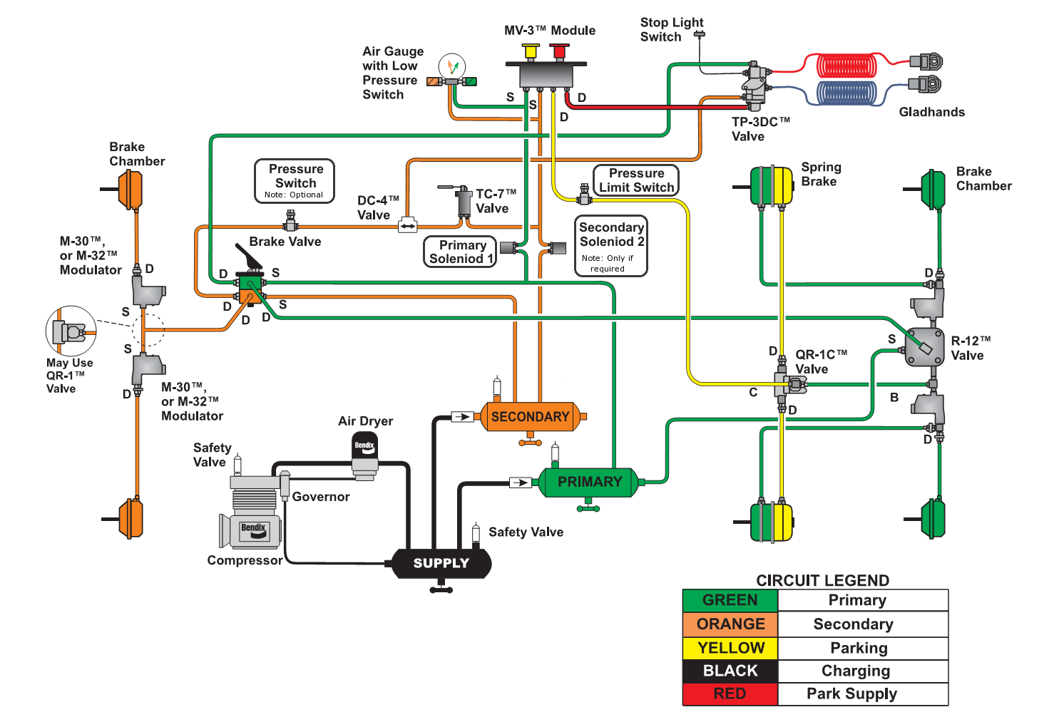
- Remove the primary supply line from the back-parking brake valve; you will need to cut the primary supply line in order to place the solenoid valve in place. Find an appropriate location to mount the solenoid.
- You may need to run an added line from the bottom port on the solenoid back to the primary supply side of the parking brake valve.
- Push the supply lines into the fittings on the solenoid making sure they lock into the position. (Fittings not included due to the multitude of installation configurations).
- Repeat steps 1-3 on the secondary supply line to the parking brake valve.
- Start the vehicle back up and charge the air system. Locate the delivery line port on the back of the parking brake valve. (This line will have pressure on it when the parking brake is released and no pressure when the parking brake is set). Either cut the line or mount the brake sensor provided to the brake valve. This sensor controls the anti-rollaway system and must be hooked to the delivery side of the brake valve so it can energize the Brakealert system when the parking brake is released.
Follow the steps below to install the seat sensor.
- Remove the bottom seat cushion from the frame.
- Flip the removed seat cushion over.
- Mount the seat sensor on the underside of the cushion between the springs or straps, approximately 6 inches from the rear of the seat.
- Install the seat back onto the frame.
- Make sure the wires are positioned so they are not pinched between the frame and cushion and exited through the rear of the seat. Make sure there is enough slack in the wire harness so that when seat height is adjusted there is no tension pulling on the wires.
- make sure to run the wires to the sear sensor under the floor mat or carpet to protect them from the environment.
- Remove the wiring harness from the box and stretch it out.
- Remove the red lock on the controller plug side of the wire harness; install the large plug into the controller. Once the plug locks into the controller be sure to reinstall the red locking pin back into the plug.
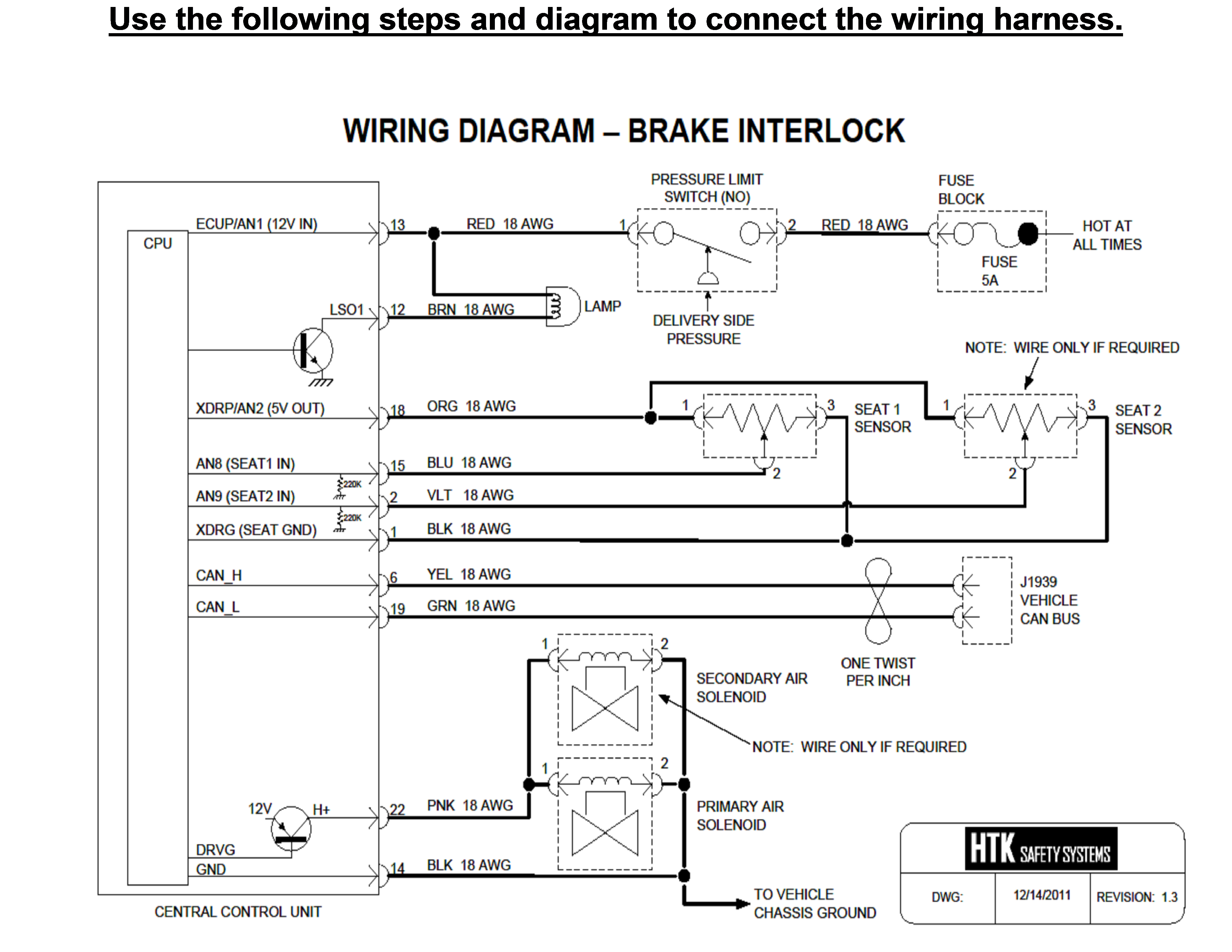
- Refer to the labeling on the wire harness and attach all the plugs to their appropriate location, making sure that all the connectors are pushed all the way in and lock into place. In some cases, there is more than enough wire needed, just roll the excess wire up and zip tie it out of the way.
- Drill a 5/16 hole in the dash and mount the LED light in a conspicuous location with an unobstructed view for the driver.
- Connect the red wire from the LED light to the red wire coming out of the wire harness with the provided connectors; next connect the black wire from the LED to the brown wire coming out of the wire harness. (This LED light will come on and notify the driver if the Brakealert system should loose contact with the vehicles CAN-BUS system.
- Connect the black ground wire from the wire harness to a good chassis ground using the provided ring connectors.
- Connect the red wire to a HOT AT ALL TIMES power source, through the fuse link provided in the kit, this line always needs to be hot in order to protect the vehicle from rollaways even when the vehicle is turned off.
READ THE FOLLOWING INFORMATION BEFORE HOOKING THE CONTROLLER TO THE CAN BUS
Vehicle J1939 Bus Connections:
To make installation easier a diagnostic port adaptor has been included with the kit. This adaptor is just an extension of the vehicles diagnostic port and will not interfere with the cummication to the port for testing/trouble shooting purposes.
If your vehicle will accept this adaptor just simply unscrew your current testing plug from under the dashboard, install the Brakealert adaptor, and reinstall to the testing port to the dash.
Next, connect the green/yellow wire from the wiring harness to the corresponding green/yellow wire coming out of the diagnostic port adaptor. If you choose not to use the adaptor provide, please use the following steps below to hook the Brakealert system to the vehicles CAN-BUS.
It is very important that the connections to the vehicle J1939 Bus be done properly and at an appropriate location to prevent problems with vehicle communications.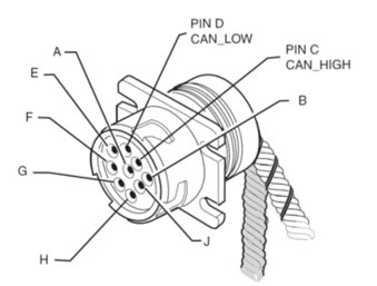
Improper connections to the J1939 Bus can result in vehicle operational and/or safety problems. Always refer to the vehicle manufacturer’s specific instructions for connecting to the J1939 network.
Connections to the J1939 Bus should only be made at designated “stub” connection points. Some manufacturers provide accessory connections that can be used. Refer to the specific vehicle service information for the presence of and locations of these connection points on the vehicle.
Determine a suitable J1939 location point. In many vehicles you can connect behind the truck diagnostic connector. Be aware that only one electronic device should be connected to the J1939 stub at the back of the diagnostic connector at a time. If another device is already present, you will need to splice directly into the vehicle’s J1939 backbone.
IMPORTANT: There should only be one device connected at this location at any time.
Pin “C” in this connector contains the CAN + Circuit (Yellow Wire) and Pin “D” contains the CAN – Circuit (Green Wire).
WARNING: Do not extend J1939 factory wires, maximum stub length is 10 feet, Minimum stub spacing is 4 inches and never have more than one ECM device on the same stub.
Follow the steps below to connect to the CAN Bus at the Diagnostic Connector:
Note: Some trucks may have activity on the J1939 bus with the door open or if an accessory is active. This can cause a faulty resistance reading on the CAN bus.
- Measure the J1939 bus resistance at the diagnostic connector. It should read between 55 to 65 ohms. Using an ohmmeter, place the positive lead on pin C and the negative lead on pin D of the diagnostic connector. Verify that the resistance is 55–65 ohms.
Note: If the test failed, you have a problem with your J1939 data bus. Stop and resolve this problem before proceeding.
- Locate the Yellow/Green Twisted Pair wires approximately 2-inches back from the diagnostic connector, (remove the outer casing of the twisted pair if necessary, to expose more of
 the wires). Refer to Vehicle J1939 Bus Connections earlier in this document.
 - Cut the Yellow and Green wires at the proper location and strip approximately ¼ inch of the wire insulation on these wires.
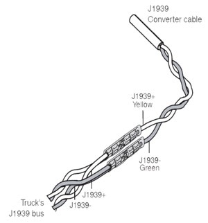
- Splice the yellow CAN high J1939+ wire from the converter cable to the yellow CAN high J1939+ wire from the truck’s J1939 bus.
- Splice the green CAN low J1939- wire from the converter cable to the green CAN low J1939- wire from the truck’s J1939 bus.
- Measure the J1939 bus resistance at the diagnostic connector. It should read between 55 to 65 ohms.
If the test failed, double-check the connections and wiring. This problem must be resolved before proceeding.
Mathematics- Mass X Speed = Energy- A 50,000lb. truck that has rolled away traveling at 7mph has 350,000  ft./lbs. of momentum on impact. To get the same impact results, a 5,000lb SUV must travel at 70mph to achieve the same 350,000 ft./lbs. of energy upon impact.
One of the most frightening sights is a moving truck without a driver behind the wheel. Because refuse and recycling trucks are very heavy and weigh up to 80,000 pounds fully loaded, once they start moving, they can pose a danger to drivers, helpers, other motorists, pedestrians, and property. Runaway trucks can crash into schools and other buildings, leading to fatalities, significant claims and bad publicity for the company and driver involved.
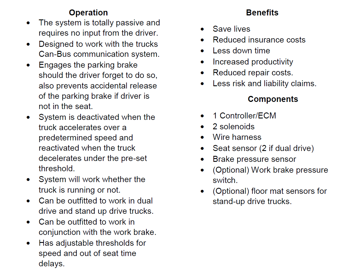
The Product: A failsafe system which prevents truck roll-aways caused by failure to set the parking brake. It consists of a seat sensor which determines if the driver is in the seat, the sensor is connected to a temper proof electronic controller which functions as the brain of the system. It monitors the sensors, truck speed, seat occupancy and parking brake status.
Please review attached link to view the system in operation.
https://www.youtube.com/watch?v=81XpZ01Bp8k.
For more information contact Tom Accardi (yfd168@optonline.net) at HTK Engineering or write to designhmi@gmail.com
The technology is Patented.
