
2023 AUTO INTERIOR DOME LAMP CONCEPT DESIGN
There are technology innovations and applications developed by Design HMI over the last few years that are ideally suited for next-generation Interior Dome Lights. The current Automotive Dome Light design aims to provide simple lighting at the lowest cost. Most OEMs’ customer value proposition for Dome Lights is minimal, like too many other generic OEM in-vehicle functions.
Below is the HMI design target for BIW Dome Light for customer-targeted feature function and Ford cost reduction. The value of higher customer satisfaction is beyond compare. Current Automotive Dome Lamo Designs are simple ON / OFF lights linked to the body system door ajar signal. The data communications from the System Architecture could be a simple two-wire signal or a single LIN-based data communication. They also have an ON/OFF Switch for the passenger to turn on the light independently after the door is closed. The same button could turn the light off if you do not want the light on when the door is ajar – for example, a sleeping baby in the rear seat.
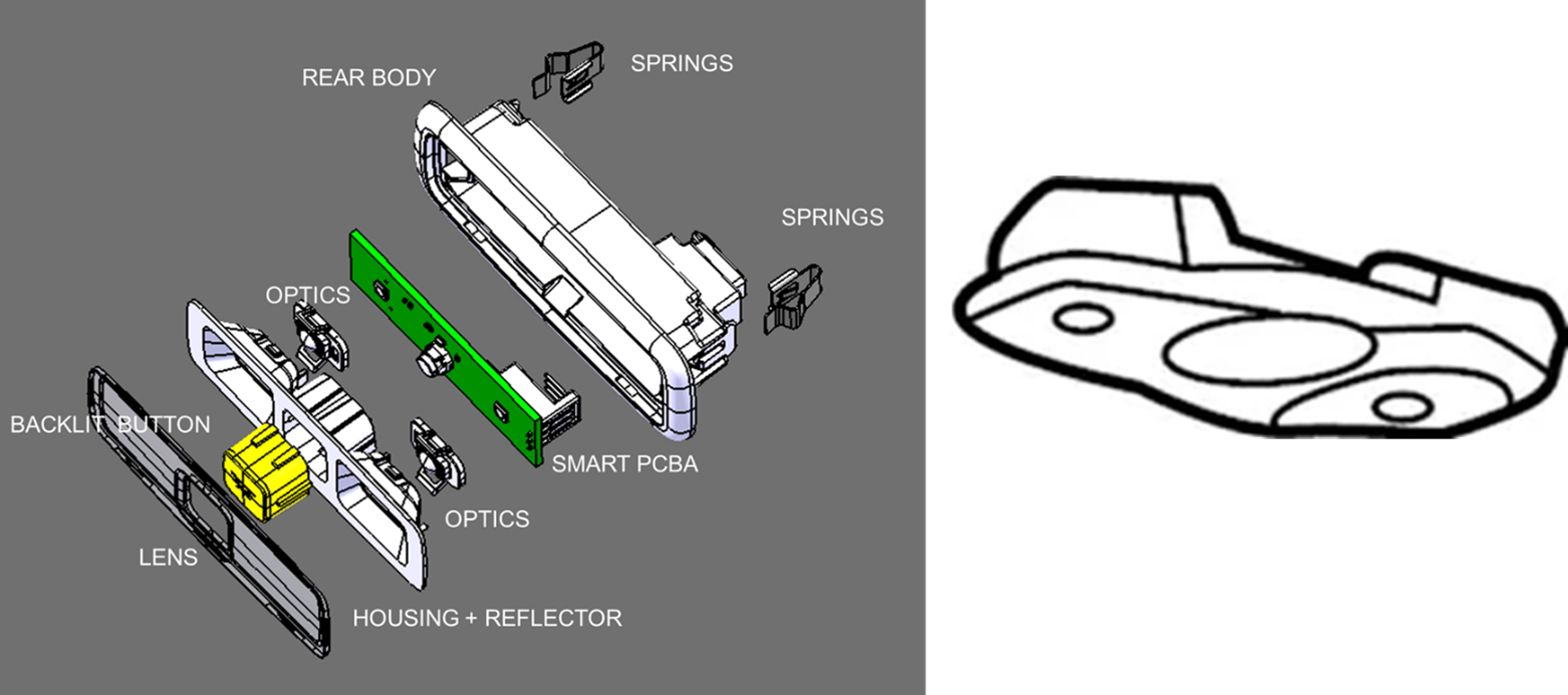
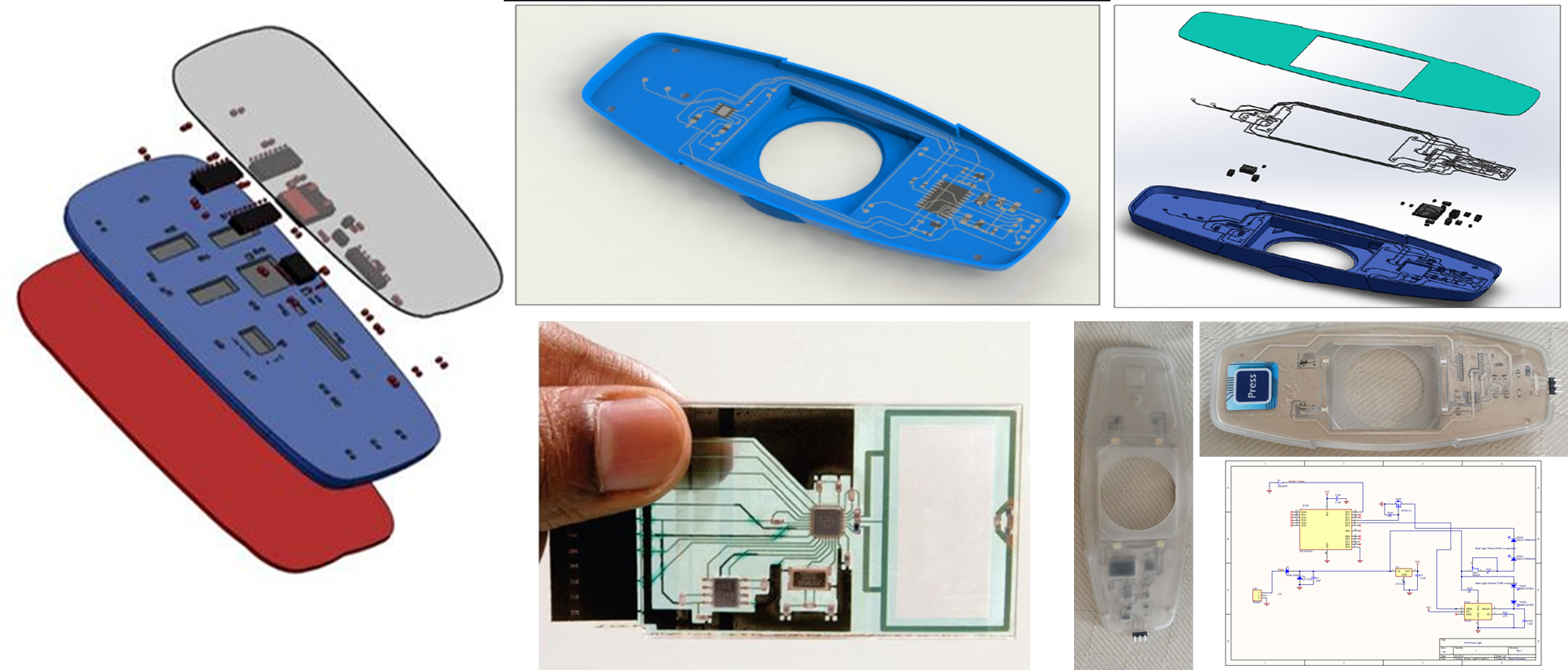
Exploded view of current in-production Ford Dome Lamp as shown below.
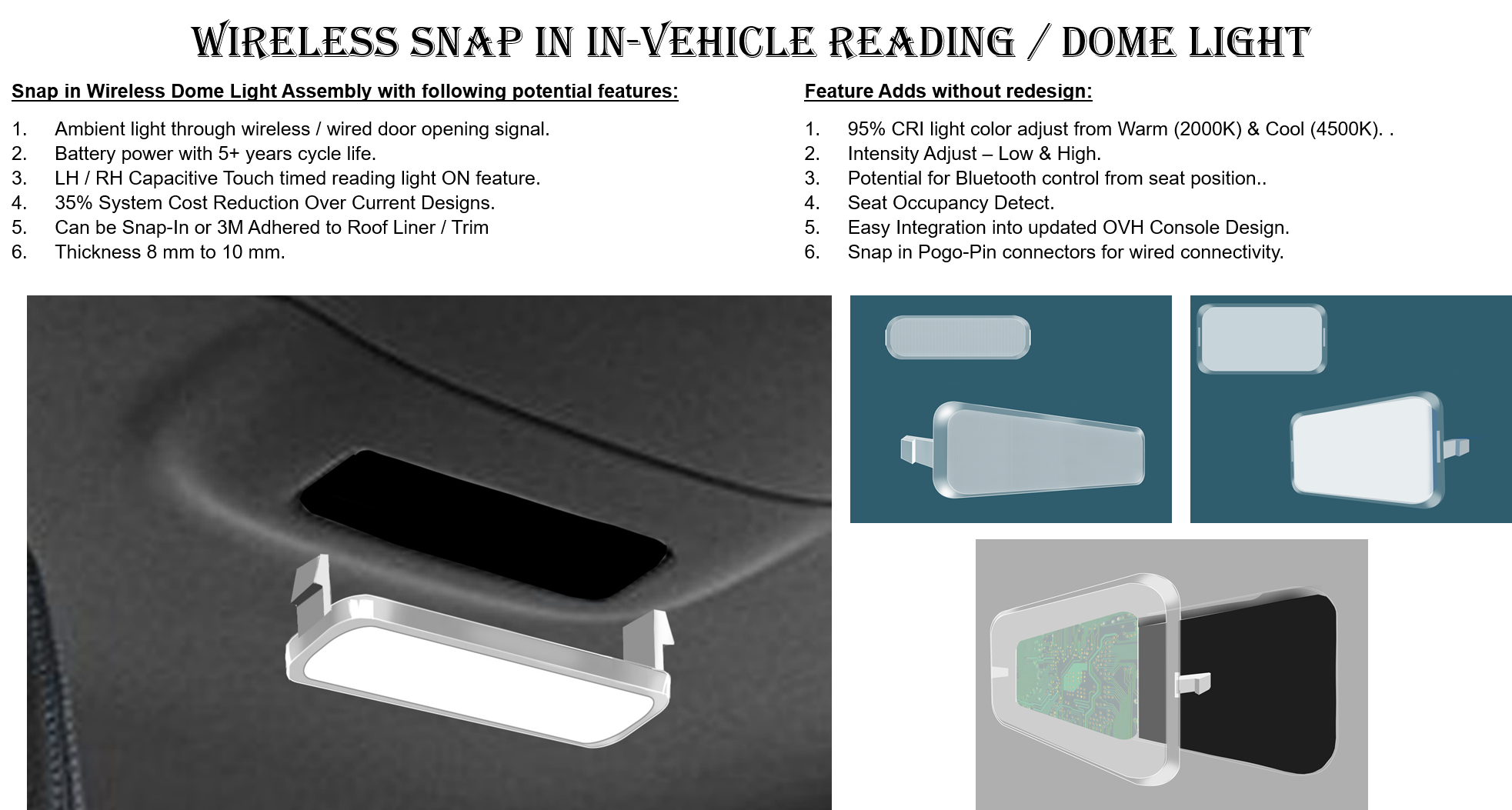
Design HMI Target for Next Generation Dome Lamp:
- Integrate lighting into the lens and eliminate Housing with a reflector.
- Eliminate the Mechanical button – capacitive touch or Elastomer Dome.
- Lit graphics for ON/OFF.
- Eliminate separate optics.
- Lighting intensity 100 Lumens at 12v (current not defined yet).
- Ramp UP / OFF targeted for 2 secs.
- System communication – wireless LIN based.
- Assembly depth < 8 mm for Snap-On integration.
- Eliminate snap in springs.
- Three levels each side independent dimming through a touch interface.
- Connector or flat wire system integration.
Options at extra cost:
- The White light color changed from 1800K to 4000K.
- Battery saves – Auto-off after 30 minutes.
- Adjustable direction for the lens – needs more investigation.
- Occupancy detection – no child left behind.
Printed Electronics Low Profile Dome Light Design
Design HMI has been developing smart Class A surfaces by integrating electronic circuits on B side of HMI Surfaces. The smart electronics is designed to meet 2018+ consumer feature requirements.
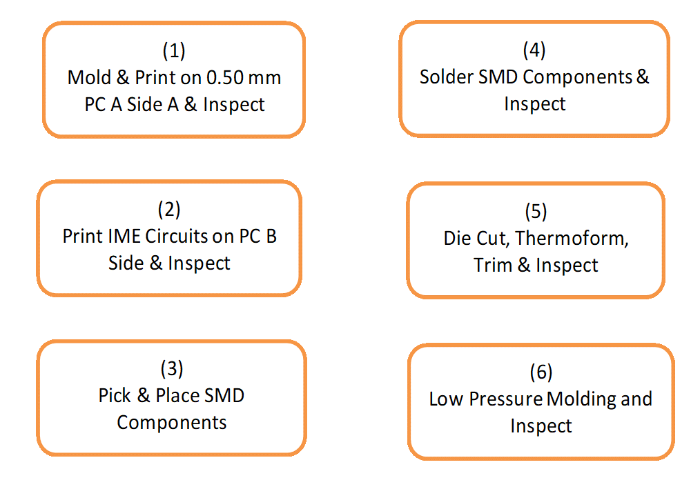
The assembly process step may be through insert molding of the formed circuit, printing of the circuit on formed assembly or through low pressure thermoforming of the assembly – no insert mold.

Other feature functions of the assembly are assumed as:
- Door Ajar light.
- LH & RH Reading Lamp with individual controls.
- Dead font backlit graphics that come on with proximity detect.
- Backlit capacitive touch without tactile feedback touch switch.
- Alternative Piezo / Snaptron Dome Contact touch input with tactile feedback.
- Abatek Polyform or equivalent Class A or standard IML / PC.
- Option to add WIFI hot spot.
- Option to add rear seat child detect sensor.
- Option for RGB door ajar light ring for hidden light glow.
- Snap fit into next assembly with Pogo Pin terminals.
- Cost target cost is $6.00
DuPont IME Conductive Ink layers:
Dielectric layers on the PC with IME circuits as below:
- Base optional layer used to provide a moisture barrier between circuit & PC base.
- White opaque (ME775) or clear (ME772) dielectric.
- Conductive Layer #1. Wide trace width to minimize resistance, especially for traces carrying LED driving current. Minimum recommended trace width is 0.025”.
- Connections to pads and cap-touch components.
- Trace lengths: minimize for minimum resistance, especially to cap-touch components

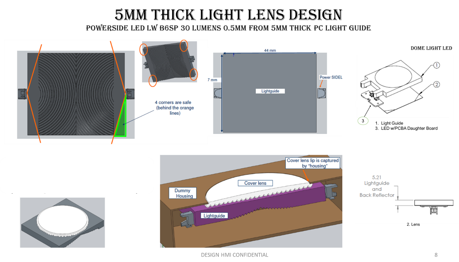
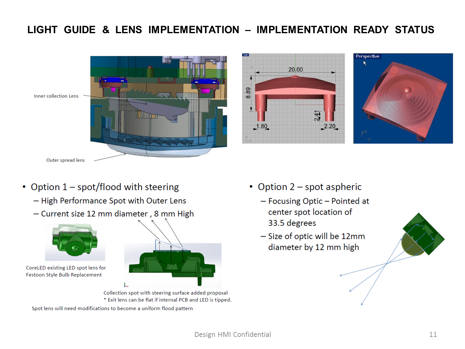
The lens design is based on snap in assembly to the molded in electronics. The LED Assembly could be part of the Lens Assembly or plastic electronics. Heat sink may need to be incorporated into the assembly base as part of the low-pressure molding process.
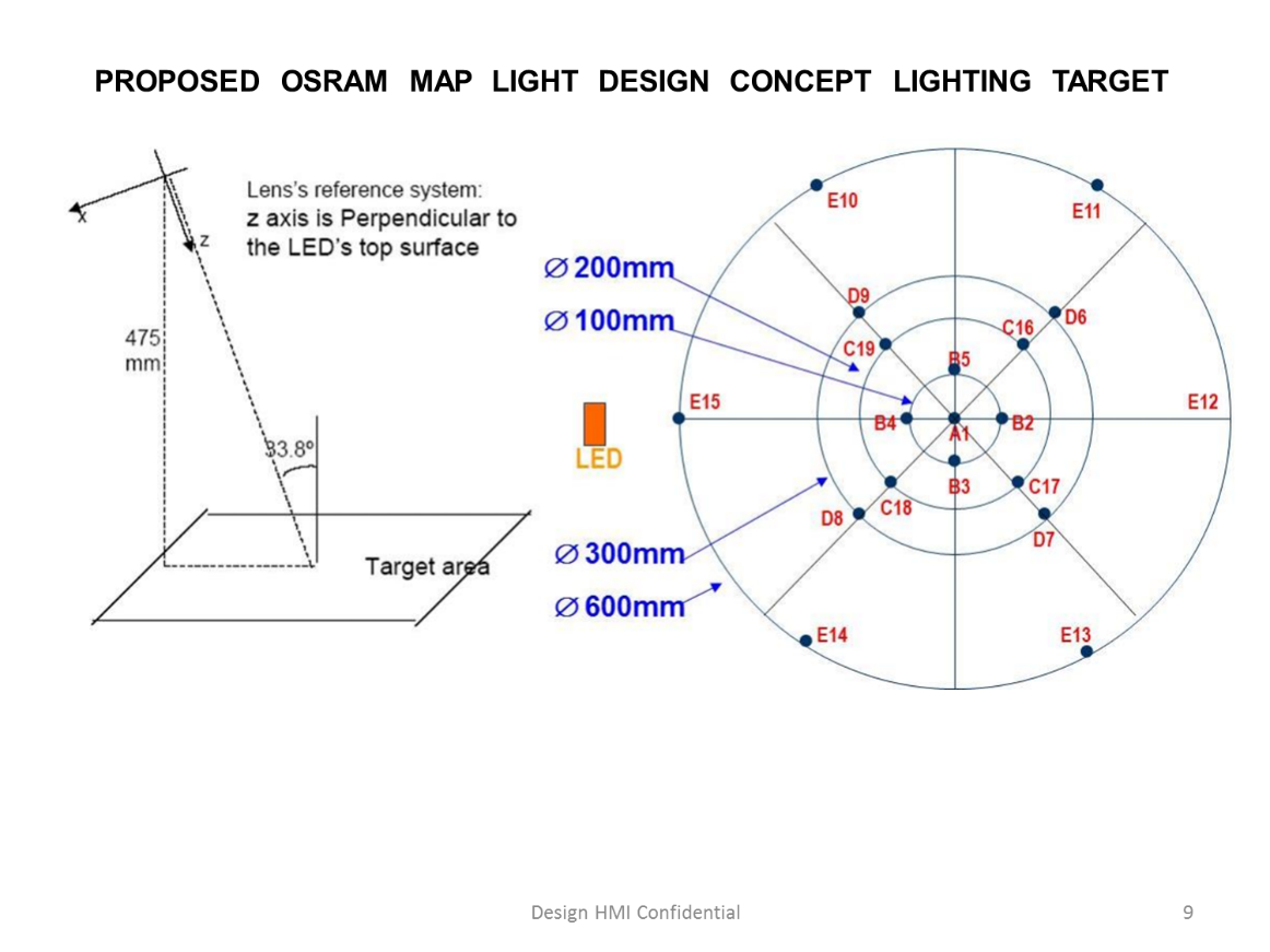
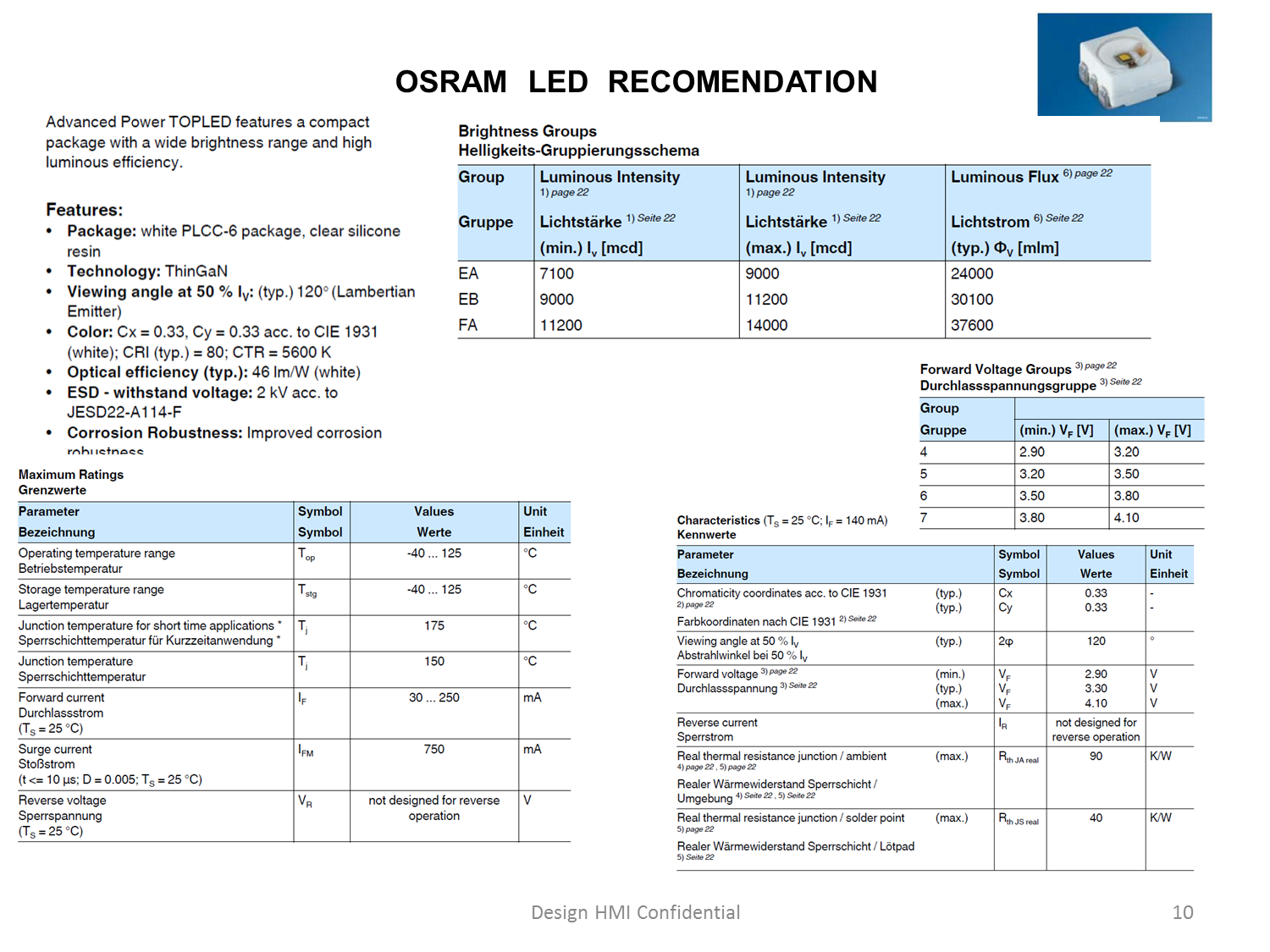
Below is the design concept for the Lens developed in collaboration with Osram Semiconductors (https://www.osram.com/os/).
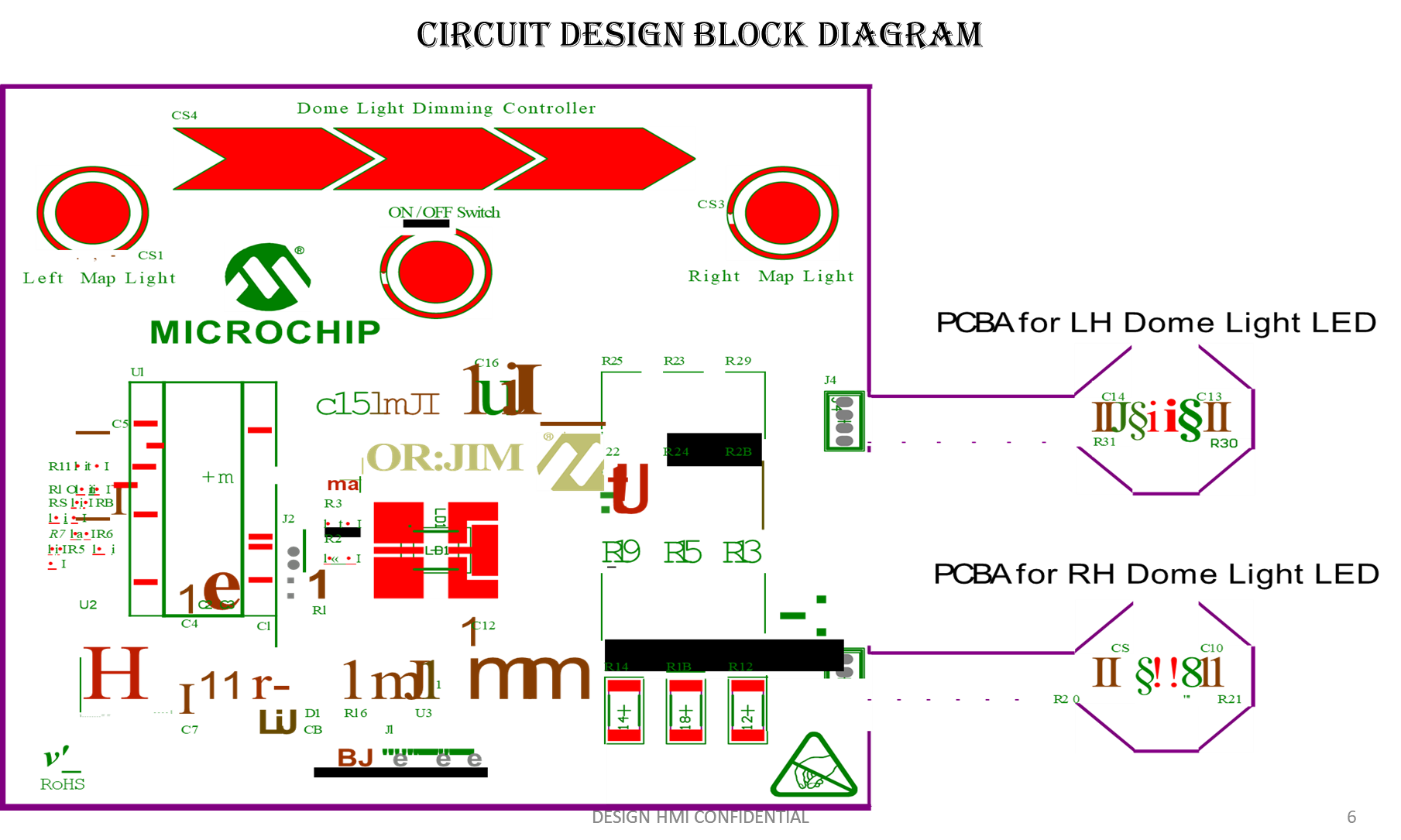
The complete electronic design was developed in consultation with Microchip Electronics (www.microchip.com) and integrator and molding specialist FZB Technology (http://fzbtechnology.com/) using DuPont IME ink and design guidelines.
For more information write to designhmi@gmail.com.
Griffith University CiP Technology – Medical, Automotive & Technologies Applications
CiP process eliminates the need for insert molding resulting in cost reduction and potential improving greatly run on line rate when in production. Also since the initial invention (patented in 2006 US20080196827 A1) and the production of prototype demonstration units (e.g. Automobile dome light housing + circuits), they have made several technical advances towards the manufacturing process.
For the last few years Griffith Edu has done more development work on their CiP technology. In 2015 Design HMI working with Griffith developed a prototype of Dome Light using their CiP technology.
Advances:
1) 3D printing (additive manufacturing). From October 2017, Griffith University will have access to a metal printer. This means that the major plastic components can be rapidly produced using injection molds formed rapidly and precisely using this new prototyping facility. These parts can then be made using the well-accepted injection molding process using almost all forms of thermoplastics. Before October, we can partner with providers in Australia to fabricate such molds.
2) Griffith University possesses a printer capable of making micro-fine, precision conductive tracks on plastic and other substrates. The range of conductive materials includes graphene, carbon black and silver. The technology greatly reduces the cost of circuit formation when compared with traditional copper interconnects.
Advantages of CiP Technology Design Dome Light:
- No etching.
- No soldering
- Only one heat step
- Environment proof
- Radio/optical transparent if required
- Electrically shielded if required
- Much lower cost
- Easy to dis-assemble mechanically
Environmental Issues with PCBA Manufacturing:
- Gaseous release (Odor)
- Liquid waste
- Energy requirements
- Disposal (recycling, re-use, land-fill)
- Shred and incinerate to recover metals
- Small workshops to remove components
- Degradability
- Directives and Legislation
- WEEE Directive (EU)
- RoHS Directive (EU)
- Basel Convention (International)
- ETS (Energy Trading Scheme)
- Cost of greenhouse gas release
CiP can have one or more of the following:
- Recycled
- Biocompatible
- Flexible or rigid
- Biodegradable
Target is to develop design concept which is Implementation Ready concept that can be quickly validated and made Application Ready for current and new programs.
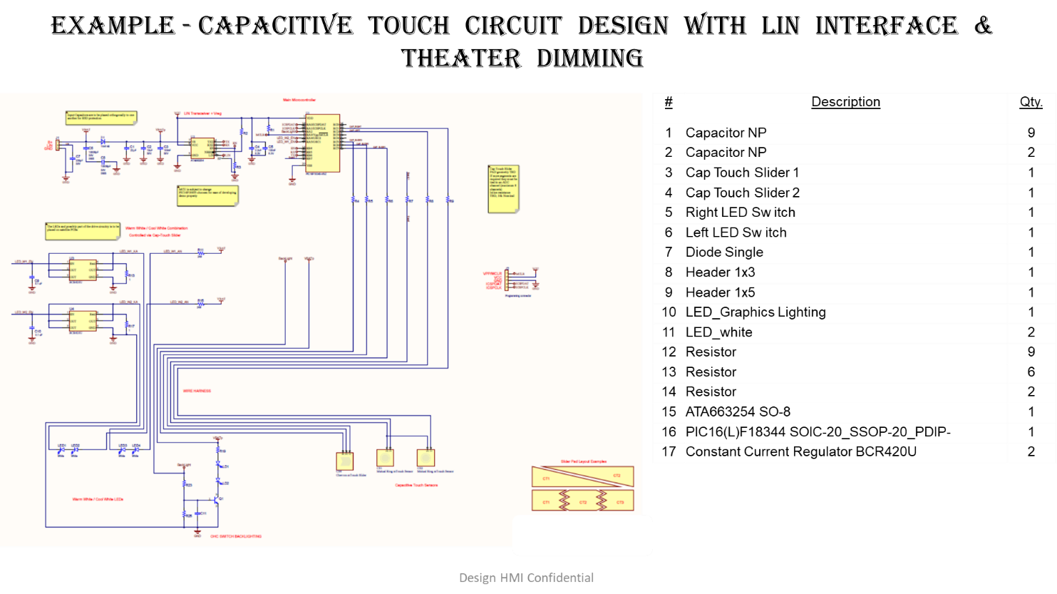
BIW design intent would be low profile assembly with theater dimming, capacitive touch with proximity sensing, LIN interface and reduced profile & package envelope.
Piece cost target would be < $5.50.
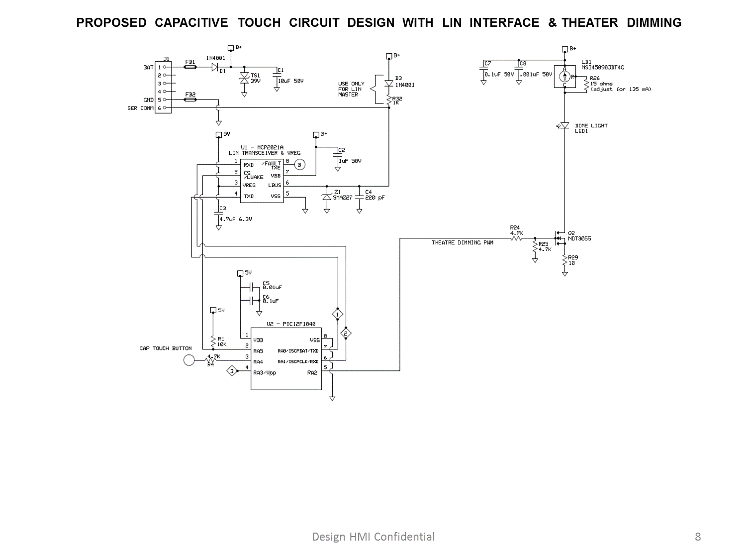
Capacitive Touch with OSRAM design LED & Lighting solution. Theater dimming and LIN interface would be design intent with lighting intensity as 46 Lux.
For more information contact designhmi@gmail.com

I’m impressed, I must say. Rarely do I come across a blog that’s equally educative and amusing, and let me tell you, you have hit the nail on the head. The problem is an issue that too few folks are speaking intelligently about. I’m very happy that I found this during my search for something relating to this.
Spot on with this write-up, I seriously feel this website needs far more attention.
I’ll probably be returning to read more, thanks for the info!