
Being developed in collaboration with FZB Technologies
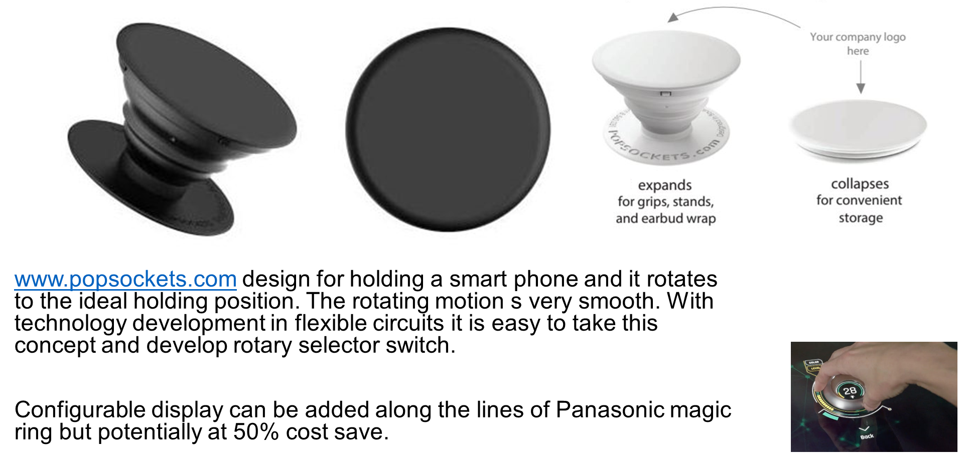
There is movement on retractable switching inputs for vehicle interiors especially in case of autonomous vehicles. One example is adding smart electronics to POPSOCKETS design as shown below.
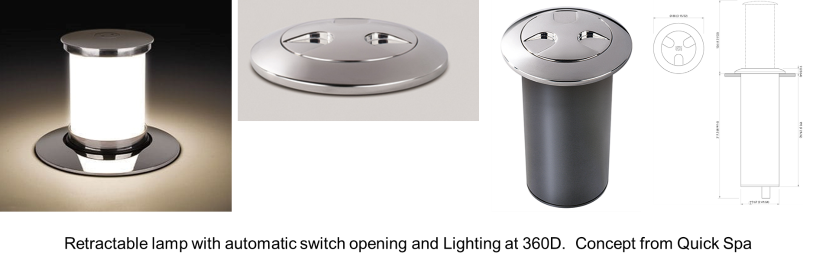
Another application for Autonomous Vehicles could be Retractable Switch Assemblies. FZB Technology has been developing one such application concept.
Key concept is:
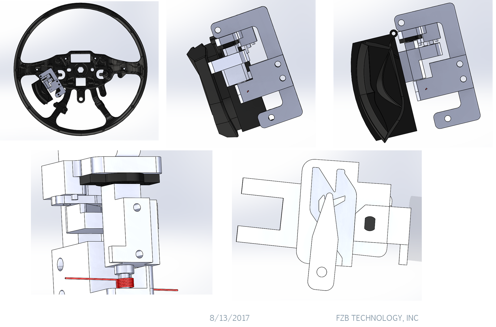
- Used the wall of the axis as profile guiding slot with a depth change on profile.
- Pin with sphere head and pre-loaded spring can stretch out and draw back.
- Torsion spring provided retraction force.
- Rotary damper slowed the retract speed.
- The speed that switch goes from hidden position to working position must be faster than pin stretch out to the hole.
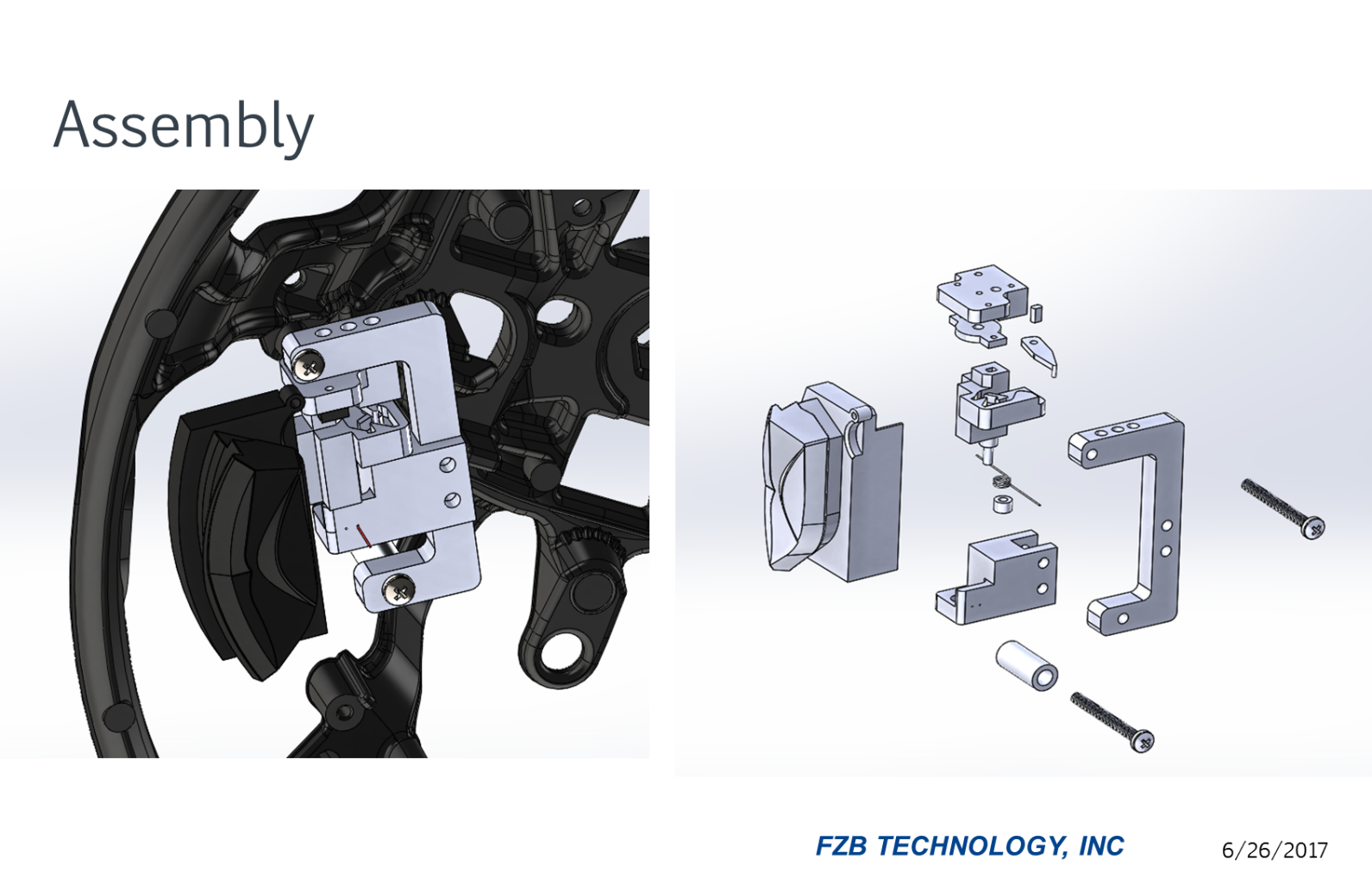
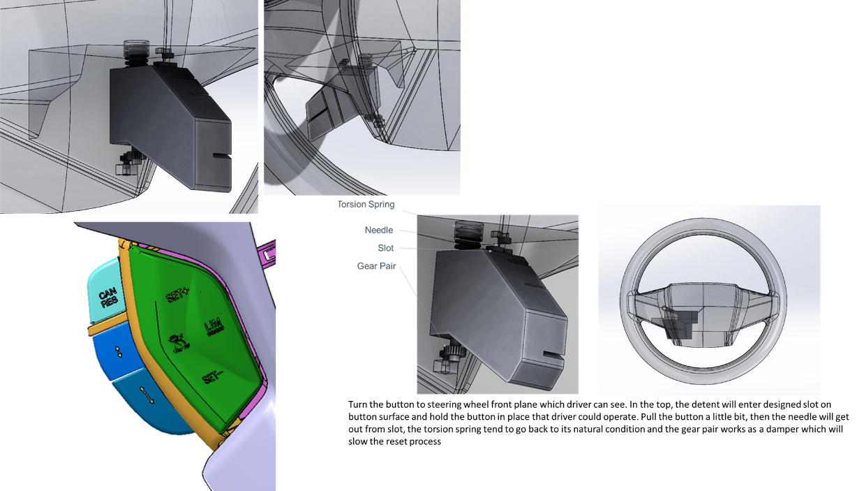
Main components:
- Designed axis with slot, torsion spring, sliding bearing, pin, rotary damper, fixture kit.
- Pin head will slide in the designed slot.
- The shape of the slot will stop and release the pin head
For specific application design contact FZB Technologies Inc or write to designhmi@gmail.com to help you link up with key engineers at FZB Technologies.
Design HMI is working with FZB to develop retractable steering wheel assembly that allows the driver to call up the switch assembly when needed.
Per initial design concept developed there is the mechanical design and the powered design with micro brushless motor.
Components for the non-powered version are: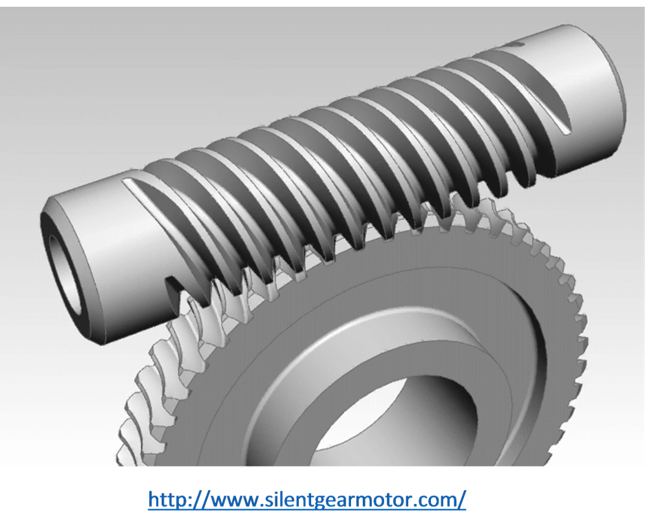
- Torsion spring
- Work and shaft gear
- Detent ball and spring
- Housing
- plastic components for assembly
Cost target per assembly for the retractable body would be $2.50 with cost of Cruise Switches (LH) and Audio Switches (RH) another $4.50 for each side.
If we want to design powered version with micro brushless motor the cost of motor assembly would be another $4.00 though it may not be necessary if the spring and gear assembly are designed as intended.
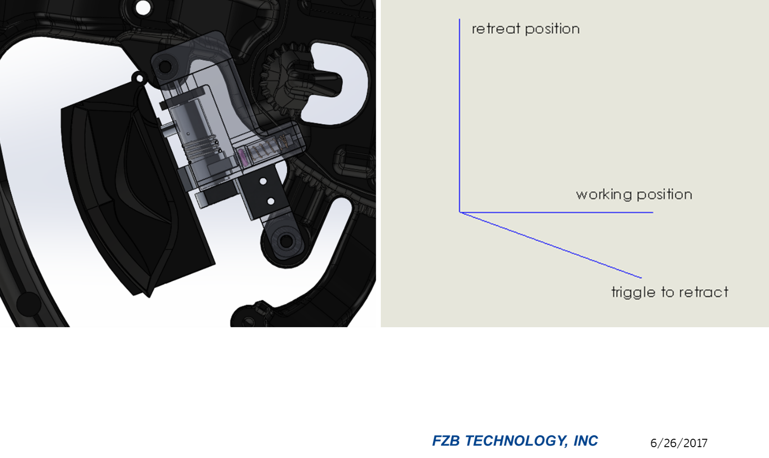
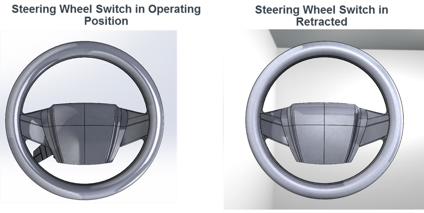
The concept design is based on Steering Wheel Switch connecting to rotation mechanism which allows it to rotate.
Pull switch from left diagram position to right diagram position and switch locks there. Pull the switch up front a little bit more then it will retreat slowly and back to left position.
The torsion spring will store energy for axle to retreat, rotary damper allows axle rotates slowly.
Pin inserts in a designed slot, the rotation axle will lock steady when pinhead travels to diagram shown position.

I loved your post.Thanks Again. Really Great.